


Overview
The USG3045M-P is a 4.5 GHz analog signal generator covering 9 kHz to 4.5 GHz with 0.001 Hz frequency resolution and a level range of −135 dBm to +25 dBm. Single-sideband phase noise typically < −122 dBc/Hz at 1 GHz / 20 kHz offset, amplitude accuracy ≤0.7 dB (Typ.), and frequency switching ≤40 ms make it suitable for both bench R&D and automated test workflows. The USG3045M-P delivers AM, FM, and ΦM analog modulation with optional pulse and narrow-pulse generation.
As an analog RF signal source, the USG3045M-P is positioned for stimulus work that depends on spectral purity and level accuracy rather than baseband modulation: component characterization, amplifier and filter testing, mixer and LNA evaluation, calibration of receivers and spectrum analyzers, and production-line stimulus for RF subassemblies. Optional pulse and narrow-pulse modulation extends the instrument into pulsed RF test for radar component validation and time-gated stimulus work, with a minimum pulse width of 20 ns and 10 ns resolution.
Key Features
- 9 kHz to 4.5 GHz Frequency Range — 0.001 Hz resolution and 0.1° phase offset step across the full band.
- −135 dBm to +25 dBm Level Range — 160 dB output range with 0.01 dB resolution and ≤0.7 dB amplitude accuracy typical.
- Phase Noise < −122 dBc/Hz at 1 GHz — single-sideband phase noise typical at 20 kHz offset, suited to sensitive receiver and component test.
- Mechanical Step Attenuator Standard — 0 to 110 dB range with 10 dB steps; mechanical attenuator delivers maximum absolute output power across all bands.
- AM, FM, and ΦM Analog Modulation — internal, external, or internal + external modulation sources from the built-in 50 MHz AWG or rear-panel input.
- Step and List Sweep — frequency and amplitude sweeps with 2 to 65,535 step points or 1 to 500 list points; LAN/USB/GPIB triggering (GPIB requires factory-installed hardware option).
- ≤40 ms Frequency Switching — SCPI, list, and step-sweep switching speed for fast automated test cycles.
- Built-in 50 MHz Function/Arbitrary Waveform Generator — standard waveforms, sweep, and modulation from a second LF output on the front panel.
- High-Stability Internal Clock Source — ≤±0.2 ppm/year aging, ≤±10 ppb temperature effects; calibration-cycle-friendly stability.
- 10 MHz Reference Input/Output — rear-panel BNC for multi-instrument synchronization.
- 5-Inch Touch Screen with Signal-Flow Interface — full touch control over every function except the power switch.
- LAN, USB Host, USB Device Standard — full SCPI automation from LabVIEW, Python, MATLAB, or Excel batch scripts; GPIB available as a factory-installed hardware option (must be ordered with the instrument).
- Web Control + Device Manager — browser-based remote access (PC and mobile) plus free PC management software (V2.5.0+).
- Optional Pulse Modulation — 80 dB on-off ratio with customizable pulse trains.
- Optional Narrow-Pulse Generator — 20 ns minimum width with 10 ns resolution for radar component test.
- Optional USB Power Sensor Support (USG3000-PK) — license-activated readback and flatness correction with a user-supplied USB power sensor.
- CE | cETLus | RoHS Compliant — meets common North American and European safety and environmental standards.
Detailed Features
High Spectral Purity for Sensitive Receiver and Component Test
Single-sideband phase noise typically below −122 dBc/Hz at 1 GHz with a 20 kHz offset is the headline spectral-purity figure that determines whether a generator can stimulate the device under test without contaminating the measurement. Low close-in phase noise matters for adjacent-channel rejection testing on receivers, image-rejection on mixers, and any narrowband filter characterization where the stimulus must be cleaner than the device's own passband behavior.
The clock-source architecture supports ≤±0.2 ppm/year aging rate, ≤±10 ppb temperature effects, and ≤±10 ppb line-voltage sensitivity — frequency reference stable enough for calibration-cycle use without external 10 MHz lock, though both 10 MHz reference input and 10 MHz output are available on the rear panel for multi-instrument synchronization.
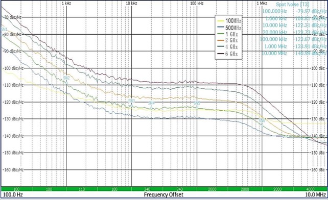 Single-sideband phase noise typical < -122 dBc/Hz at 1 GHz
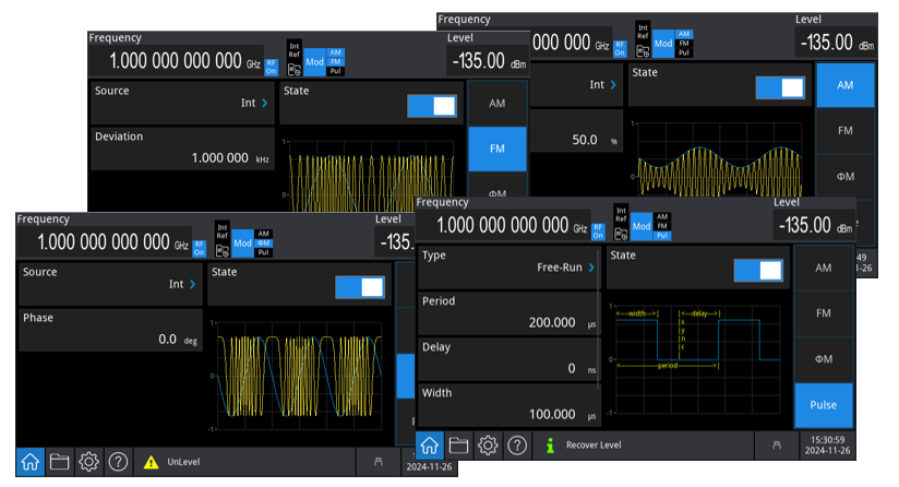 AM, FM, and ΦM with internal, external, and combined modulation sources
Analog Modulation — AM, FM, and ΦM
Amplitude, frequency, and phase modulation are all standard. Each mode supports three modulation-source paths: internal (from the built-in 50 MHz function/arbitrary waveform generator), external (via the rear-panel analog modulation input), or internal + external combined for layered modulation. Internal modulation eliminates the second-instrument dependency for most R&D and component-test workflows, simplifying both bench setup and automated test fixturing.
Modulation parameters — depth, rate, and waveform shape — are accessible through the touch UI's signal-flow-guided interface, which keeps the modulation source, modulation type, and RF carrier visible together on one screen rather than buried in separate menus.
 160 dB output range with three ALC modes
Wide Output Range — +25 dBm Maximum, −135 dBm Minimum
Output settable range is −135 dBm to +25 dBm with 0.01 dB resolution. Maximum output power varies by frequency band and attenuator type: in the 250 MHz to 1.2 GHz band, the electronic attenuator delivers +20 dBm typical, while the mechanical attenuator option reaches +24 dBm. Above 1.2 GHz and through 3.6 GHz, electronic output is +18 dBm; mechanical-attenuator output is +22 dBm.
Three ALC (Automatic Level Control) modes are available: ALC Auto selects the optimum mode for the current operating state; ALC On runs closed-loop level control for CW, FM, and ΦM operation; ALC S&H (Off) freezes the closed-loop value on frequency or amplitude transitions, useful for AM and pulse modulation work where ALC interaction with the modulation envelope is undesirable.
Optional Pulse and Narrow-Pulse Generation
The optional pulse modulation package adds an on-off ratio of up to 80 dB with customizable pulse-train definitions, enabling single-instrument pulsed RF for radar component test, time-gated stimulus, and EMC pulsed-emission work. The narrow-pulse generator option extends capability to a 20 ns minimum width with 10 ns resolution, addressing test requirements of millimeter-wave radar components used in commercial automotive ADAS suppliers and short-range industrial radar systems.
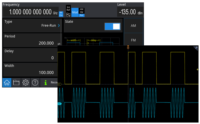 Pulse modulation with 80 dB on-off ratio and narrow-pulse generation
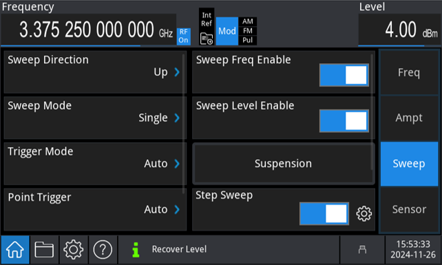 Step and list sweep on frequency and amplitude with bus triggering
Frequency and Amplitude Sweep, Built-in 50 MHz AWG
Step sweep and list sweep are both standard on frequency and amplitude. Step sweep supports 2 to 65535 points; list sweep supports up to 500 user-defined points with per-point dwell times from 100 μs to 100 s. Sweep change is selectable linear or logarithmic. Trigger sources include free-running, external trigger, front-panel key, and bus (LAN, USB, GPIB) — full automated-test compatibility without manual intervention.
A built-in 50 MHz function/arbitrary waveform generator provides standard waveforms, sweep, and modulation in the same chassis. The LF output sits on the front panel alongside the RF output, so dual-output stimulus work doesn't require a second instrument on the bench.
USB Power Sensor Support — Flatness Correction at the DUT Plane (Option USG3000-PK)
The optional USG3000-PK software license enables the instrument to read and display power measurements from a user-supplied USB power sensor connected to the front-panel USB Host port. The license is delivered as a file that installs from a USB stick via the instrument's Option Install menu, following the same activation workflow as the Pulse Modulation and GPIB options. A USB power sensor is not included; the user supplies a compatible sensor.
Once activated, the Power Sensor menu provides measurement frequency entry, frequency coupling to the current RF carrier (with multiplier and offset for harmonic and IF-shifted measurements), measurement averaging, and amplitude offset entry — the standard tools for flatness correction and cable-loss compensation at the DUT plane. The amplitude offset entry is particularly useful when the signal path between the generator and the device under test includes cables, attenuators, or amplifiers: the displayed power reflects what the DUT actually sees, not what leaves the generator's output connector.
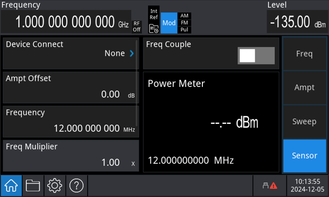 License-activated USB power sensor support — user supplies sensor
5-Inch Touch UI with Signal-Flow Interface
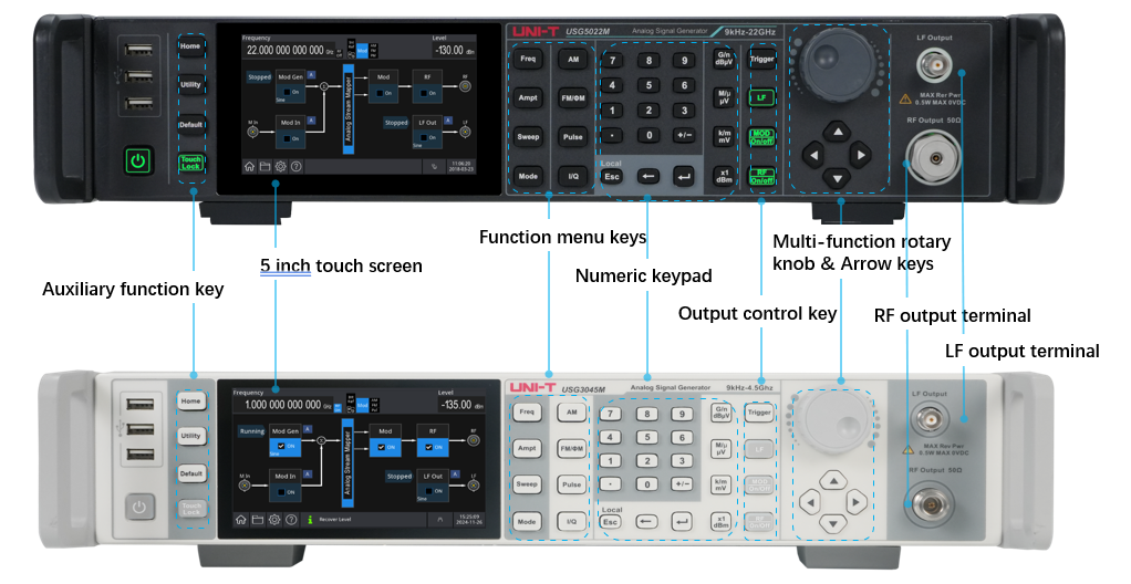
A 5.0-inch high-resolution touch screen provides full touch control over every function except the power switch. The interface is built around a signal-flow diagram — the user sees modulation source, modulation type, sweep mode, and RF carrier as a connected chain rather than as scattered menu items. For an instrument with this much configurable surface area (multiple modulation paths, multiple sweep modes, optional pulse and power-meter kits), the signal-flow paradigm meaningfully cuts setup time on R&D benches where the test configuration changes hour-to-hour.
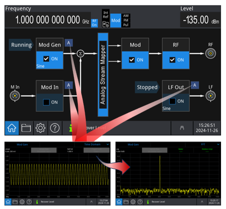 5-inch touch screen with signal-flow-guided interface
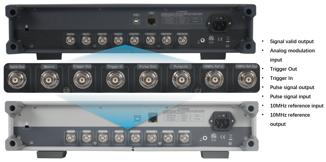 LAN, USB, GPIB (factory option) with SCPI, Web Control, and Device Manager
Full Automation — SCPI, Web Control, Device Manager
LAN, USB Host, and USB Device are standard rear-panel interfaces. GPIB is available as a factory-installed hardware option and must be ordered with the instrument. All ports speak the standard SCPI command set, enabling remote operation from any automation-capable host. Test engineers commonly drive the instrument from LabVIEW, Python, MATLAB, or even Excel macros for batch command execution.
Web Control provides browser-based remote access — point a PC or mobile browser at the instrument's IP address and the full front-panel UI is available remotely, with no client install. Device Manager (UNI-T's free PC software, V2.5.0 and higher) manages the instrument via LAN (VXI-11, Socket), USB Device (USB-TMC), or GPIB, and handles batch instrument inventories on a multi-station test floor.
Detailed Specifications
| Frequency range | 9 kHz to 4.5 GHz |
|---|---|
| Frequency resolution | 0.001 Hz |
| Phase offset step | 0.1° |
| Frequency switching speed | ≤40 ms (SCPI / list / step sweep) |
| Level settable range | -135 dBm to +25 dBm |
| Level resolution | 0.01 dB |
| Amplitude accuracy (Typ.) | ≤0.7 dB |
| Attenuator type | Mechanical step attenuator standard (0 to 110 dB, 10 dB steps) |
| Max output (mech.) — 1.2 GHz band | +24 dBm |
| Max output (mech.) — 3.6 GHz band | +22 dBm |
| Max output (elec.) — 1.2 GHz band | +20 dBm |
| Max output (elec.) — 3.6 GHz band | +18 dBm |
| Phase noise (Typ.) | <-122 dBc/Hz @ 1 GHz, 20 kHz offset |
| Oscillator aging rate | ≤ ±0.2 ppm/year |
| Temperature effects | ≤ ±10 ppb |
| Initial calibration accuracy | ≤ ±40 ppb |
| Analog modulation | AM, FM, ΦM (internal / external / internal+external) |
| Pulse modulation (option) | 80 dB on-off ratio, customizable pulse trains |
| Narrow pulse (option) | Min width / resolution: 20 ns / 10 ns |
| USB power sensor (option USG3000-PK) | License-activated; flatness correction with user-supplied USB power sensor |
| Sweep modes | Step sweep, list sweep (frequency, amplitude) |
| Step sweep points | 2 to 65535 |
| List sweep points | 1 to 500 |
| Dwell time | 100 μs to 100 s |
| Built-in AWG | 50 MHz function / arbitrary waveform generator |
| Reference (10 MHz) | 10 MHz (in/out, 50 Ω) |
| Display | 5.0-inch touch screen, signal-flow-guided interface |
| Standard interfaces | LAN, USB Host, USB Device (GPIB optional) |
| Remote control | SCPI, Web Control (browser), Device Manager (PC software, V2.5.0+) |
| Certifications | CE | cETLus |
| RoHS | Compliant |
Specifications subject to change without notice. "Typ." values represent typical performance and are not warranted.
Applications
Wireless and RF Component Development
- Higher-Power Sub-6 GHz Bench R&D — Mechanical attenuator delivers +24 dBm at 1.2 GHz for amplifier compression-point and 1 dB-CP measurements on receiver front-ends and high-side LNAs.
- Filter and Amplifier Sweeps — Built-in step and list sweep on frequency and amplitude with external trigger sync for automated test fixturing.
- Mixer Characterization — Dual-output (RF + LF) on a single chassis — mixer LO, RF input, and IF measurement without a second instrument.
- Receiver Pre-selector Testing — High spectral purity (phase noise < −122 dBc/Hz at 1 GHz) for image-rejection and adjacent-channel testing.
Commercial Production Test and Calibration
- Production-Line Stimulus for RF Modules — Mechanical attenuator's higher absolute output supports compression-class spec verification on commercial RF module production lines.
- USB Power Sensor Integration — Optional USG3000-PK license activates flatness correction at the DUT plane with a user-supplied USB power sensor.
- Frequency Coupling — Sensor automatically tracks carrier sweeps for cable-loss verification across the full output range.
- Full SCPI Automation — LAN, USB, or GPIB (factory-installed option) — drop-in for existing automated test stations running LabVIEW, Python, MATLAB, or Excel.
Pulsed-RF Stimulus for Commercial Radar Components
- Higher-Power Pulsed-RF for Radar TR Modules — Mechanical attenuator combined with narrow-pulse generator option supports high-fidelity radar front-end and TR-module test.
- 80 dB On-Off Ratio Pulse Modulation — Dynamic-range testing on radar TR modules and pulsed-RF receivers.
- Customizable Pulse Trains — User-defined PRI emulation for radar timing characterization.
- External Pulse Trigger I/O — Synchronization with radar receiver test fixtures and external trigger sources.
Accessories & In the Box
Included
- USG3045M-P RF signal generator
- AC power cord (region-specific)
- USB data cable
- Quick start guide and certificate of conformity
Recommended Accessories
- USG3000-PM — Pulse modulation option (license-activated; 80 dB on-off ratio, customizable pulse trains).
- USG3000-PG — Narrow-pulse generator option (license-activated; 20 ns minimum width, 10 ns resolution).
- USG3000-PK — USB power sensor support option (license-activated; user supplies a compatible USB power sensor).
- USG3000-GPIB — GPIB interface hardware option; adds a factory-installed IEEE 488 port for legacy automation systems. Must be ordered with the instrument — cannot be added after purchase.
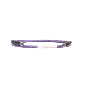
- SMA cables and adapters — UT-W01-6GHz NJ-NJ DC-6 GHz cable, UT-W02-6GHz SMAJ-NJ DC-6 GHz cable, UT-C01-6GHz SMA-N adapter, UT-C02-4GHz N-BNC adapter.
Family Members
- USG3045M — 4.5 GHz analog, electronic attenuator.
- USG3065M — 6.5 GHz analog, electronic attenuator.
- USG3065M-P — 6.5 GHz analog, mechanical attenuator.
- USG3045V — 4.5 GHz vector, electronic attenuator.
- USG3045V-P — 4.5 GHz vector, mechanical attenuator.
- USG3065V — 6.5 GHz vector, electronic attenuator.
- USG3065V-P — 6.5 GHz vector, mechanical attenuator.
Frequently Asked Questions
What is the difference between the USG3045M-P and the non-−P variant?
The USG3045M-P ships with an mechanical step attenuator as standard; the non-−P variant substitutes an electronic step attenuator. Both provide 0–110 dB range with 10 dB steps. Mechanical attenuators deliver higher absolute output power (~+4 dB above electronic at the 250 MHz–3.6 GHz bands); electronic attenuators switch faster and have longer service life. Choose mechanical for maximum output headroom, electronic for high-cycle automation.
What automation interfaces are standard?
LAN, USB Host, and USB Device are standard rear-panel interfaces. GPIB is available as a factory-installed hardware option (must be ordered with the instrument). All ports support the standard SCPI command set, so the instrument drops into any existing automated test station (LabVIEW, Python, MATLAB, Excel) without protocol translation. Web Control provides browser-based remote access via the instrument's IP address — no client install required, works from PC and mobile. UNI-T's free Device Manager PC software (V2.5.0 and higher) handles batch instrument inventories via LAN (VXI-11, Socket), USB Device (USB-TMC), or GPIB.
What does the USG3000-PK power sensor option provide?
USG3000-PK is a software license that activates USB power sensor support in the instrument. The user connects a compatible USB-TMC power sensor (sold separately) to the front-panel USB Host port; the instrument displays the power measurement on its own screen with menu controls for measurement frequency, frequency coupling (multiplier + offset), amplitude offset for path-loss compensation, and averaging. The primary use case is flatness correction and cable-loss compensation at the DUT plane — the amplitude offset entry compensates for cables and adapters between the generator and the device under test. License is activated via UNI-T's standard option-install workflow.
Warranty
This instrument is backed by UNI-T's 3+2 Year Warranty — 3 years of standard coverage, plus 2 additional years free when you register your product. That's 5 years of total protection at no extra cost.
The warranty covers manufacturing defects and component failures under normal use conditions. UNI-T instruments are built for professional daily use, and our warranty reflects that commitment to long-term reliability.
| Frequency Range | 9kHz - 4.5GHz | ||||||||
|---|---|---|---|---|---|---|---|---|---|
| Modulation Types | AM|FM|ΦM|Pulse | ||||||||
| Mechanical Attenuator | ✓ | ||||||||
| Instrument Type | Analog RF Generator | ||||||||
| Maximum Output Power |
|
||||||||
| Phase Noise |
|
Features
- LF Generator
- Touch Screen
Full specifications (40)
| Details | |||||||
|---|---|---|---|---|---|---|---|
| Level Range | -135dBm - +25dBm | ||||||
| Level Accuracy | ≤0.7dB | ||||||
| Level resolution | 0.01dB | ||||||
| Frequency Resolution | 0.001Hz | ||||||
| Phase offset step | 0.1° | ||||||
| Frequency switching speed | ≤40ms | ||||||
| Step Attenuator | 0 - 110dB (10dB steps) | ||||||
| Sweep Type | List|Step | ||||||
| Sweep Points | 2 - 65535 (step)|1 - 500 (list) | ||||||
| Dwell time | 100μs - 100s | ||||||
| Harmonics |
|
||||||
| Non-harmonics |
|
||||||
| SWR | <1.8:1 | ||||||
| Pulse On-off Ratio | ≥80dBc (1MHz - 4.5GHz) | ||||||
| Narrow Pulse Width (min) | 40ns (option) | ||||||
| AM Depth | 0 - 100% | ||||||
| Reference Frequency | 10MHz in/out (50Ω) | ||||||
| Oscillator aging rate | ≤±0.2ppm/year | ||||||
| Initial calibration accuracy | ≤±40ppb | ||||||
| AWG Channels | 1 | ||||||
| AWG Frequency | 50MHz | ||||||
| Channels | 1Ch | ||||||
| Standard Waveforms | Sine|Square|Pulse|Triangular|Arbitrary|DC|Noise | ||||||
| Lf Frequency Range | 0.001Hz - 50MHz (sine) | ||||||
| Lf Amplitude Range | 1mVpp - 2Vpp | ||||||
| Lf Modulation | AM|FM|ΦM|Pulse|ASK|FSK|PSK|QAM | ||||||
| Features | |||||||
| Lf Sweep Modes | Linear|Logarithmic|Step | ||||||
| Lf Waveforms | Sine|Square|Pulse|Triangular|Arbitrary|DC|Noise | ||||||
| Built-in Signal Generator | Included | ||||||
| General Information | |||||||
| Display Size | 5in | ||||||
| Display Type | TFT LCD | ||||||
| Display Resolution | 800×480 | ||||||
| RF Connector | N-type (50Ω) | ||||||
| Interface | LAN|USB-Host|USB-Device (GPIB optional) | ||||||
| Power Consumption | <75W | ||||||
| Temperature effects | ≤±10ppb | ||||||
| Dimensions (W×H×D) | 449 × 100 × 474 mm | ||||||
| Weight | <20 kg | ||||||
| Warranty | 3+2 years | ||||||
| Certifications | CE|cETLus | ||||||
Data Sheets and Manuals
Check your instrument’s hardware revision before updating firmware — different hardware revisions take different builds.
Authentic UNI-T accessories are an affordable way to extend the functionality of your instrument.
USG3000 Options 4
Need to add specific functionality to your UNI-T instrument? Here are our options for specific applications and measurement types. Have a question? Contact us at 888-668-UniT (8648).


RF Accessories 11
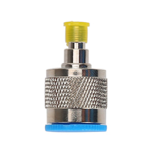
UT-C01-6 GHz Adapter
$29.00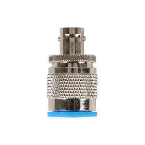
UT-C02-4 GHz Adapter
$29.00
UT-C03-18 GHz Adapter
$79.00
UT-C04-40 GHz Adapter
$79.00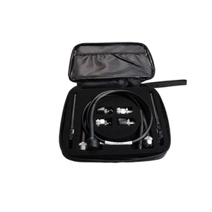
UT-CK01 Utility Kit
$262.00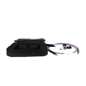
UT-CK02 Utility Kit
$389.00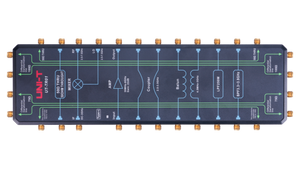
UT-TR01 RF Demonstration Board
$1,049.00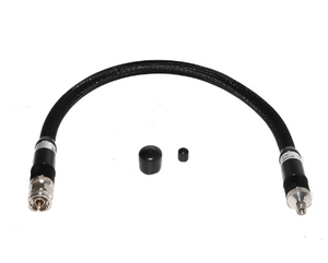
UT-VNA18-3.5M-NM VNA Test Cable Kit (18 GHz)
$525.00
UT-W01-6 GHz N-N RF Cable
$55.00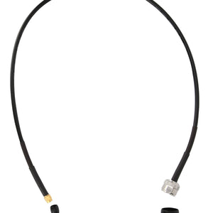
UT-W02-6 GHz N-SMA RF Cable
$55.00