Now's The Time To Save
Save $1,000's on UNI-T Spectrum Analyzers and Oscilloscopes. Bundles and Discounts available until 03/31/26 on UTS1000, UTS3000, MSO2000X, MSO3000X, and MSO7000X. Learn more about the bundles here.
Check out our CLEARANCE Section for unbelievable savings.


Uni-Trend Spectrum Analyzer Accessories
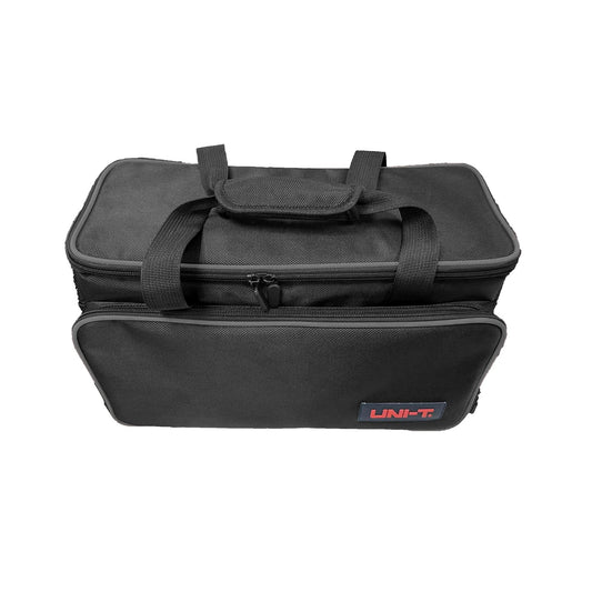
BAG-B3 Carry Bag for UTD UTS1000/3000 MSO/UPO1000/2000/3000 Models
52 In Stock
Soft carrying bag that fits UTD Digital Storage Oscilloscopes, MSO/UPO1000/2000/3000 Mixed Signal and Ultra Phosphor Oscilloscopes, and UTS1000/3000 Spectrum Analyzers.
$65.00
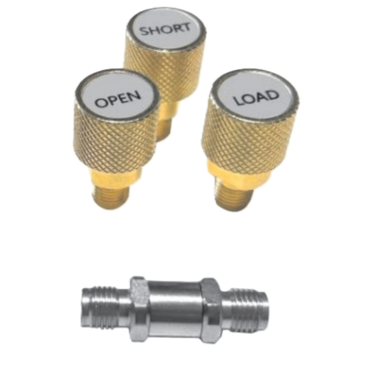
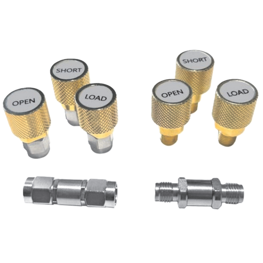
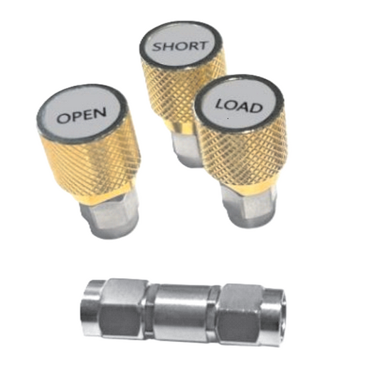
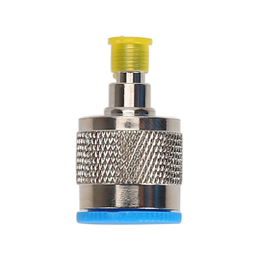
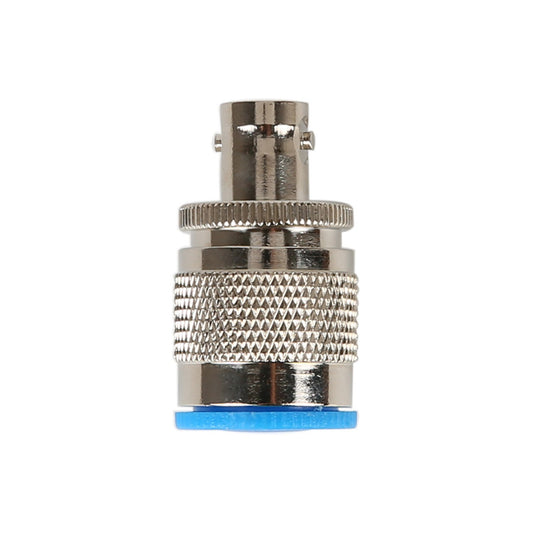
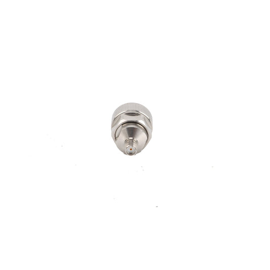
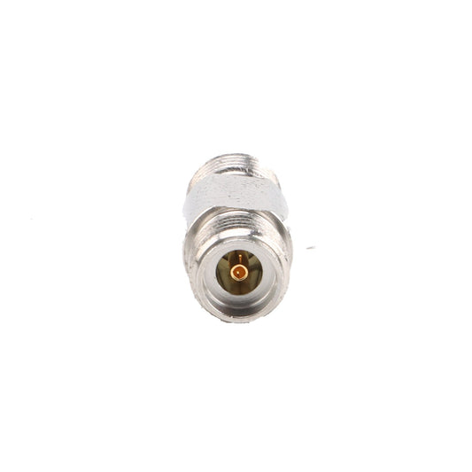
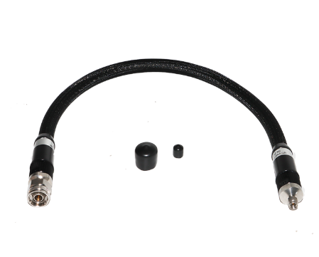
UT-3009F/M Female-Male VNA Calibration Kit (9GHz)
130 In Stock
Female-Male VNA Calibration Kit (9GHz)
$1,699.00


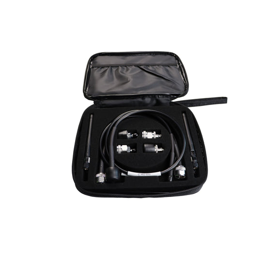

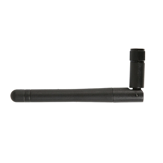
UT-CK01 Utility Kit
75 In Stock
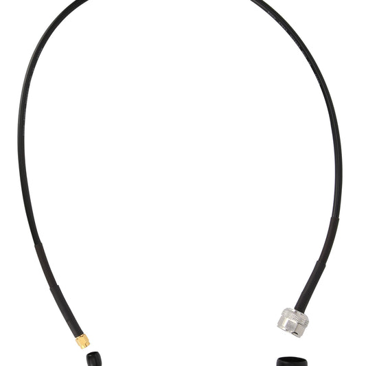
Spectrum Utility Kit: includes NSMAJ-NJ-0.7M DC-6G Cable x1, NJ-NJ-0.7M DC-6G Cable x1, SMA-N-KJ-T DC-6GHz Adapter x2,N-BNC-JK DC-4GHz Adapter x2, 2400MHz-2500MHz Antenna x2, 824-960MHz/1710-1990MHz x2
$249.00

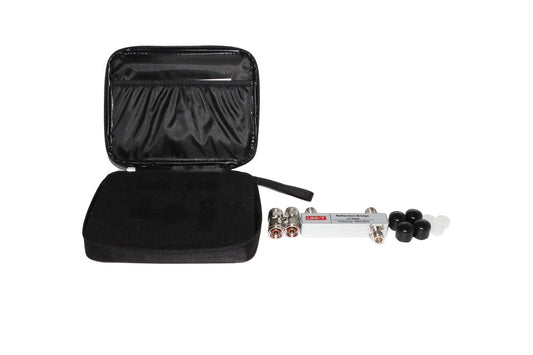

UT-RB60 VSWR Reflection bridge for spectrum analyzer (6GHz)
10 In Stock
UT-RB60 VSWR Bridge - Reflection Measurement Solution
Expand Your UTS3000T+ Series Capabilities
The UT-RB60 VSWR Bridge is the essential accessory for engineers and technicians who need accurate reflection measurements with their UTS3000T+ Series spectrum analyzers. This precision instrument transforms your spectrum analyzer into a comprehensive reflection measurement system, enabling critical antenna and transmission line analysis across the entire UTS3000T+ product family.
Key Features
Wide Frequency Coverage
Operating Range: DC to 6 GHz
Compatible with the complete UTS3000T+ series:
UTS3015T+ (9 kHz to 1.5 GHz)
UTS3032T+ (9 kHz to 3.2 GHz)
UTS3036T+ (9 kHz to 3.6 GHz)
UTS3084T+ (9 kHz to 8.4 GHz)
Covers all major communication bands including cellular, WiFi, Bluetooth, and emerging 5G/6G frequencies
Precision Measurement Capabilities
VSWR (Voltage Standing Wave Ratio) measurement
Return Loss analysis
Reflection Coefficient determination
High accuracy across the entire frequency range
Professional Build Quality
Robust construction for laboratory and field use
Type-N connectors for reliable, low-loss connections
50Ω impedance matching for standard RF systems
Compact, portable design for on-site measurements
Applications
Antenna Testing & Optimization
Measure antenna VSWR across operating bandwidth
Identify resonant frequencies and bandwidth characteristics
Optimize antenna matching for maximum power transfer
Transmission Line Analysis
Verify cable integrity and performance
Locate impedance discontinuities
Assess connector quality and installation
RF System Validation
Component matching verification
Filter and amplifier input/output characterization
Quality control in manufacturing environments
Technical Advantages
Seamless Integration
The UT-RB60 works directly with your UTS3000T+ series analyzer's built-in reflection measurement functions. Simply connect the bridge between your spectrum analyzer and the device under test - no complex setup required.
Advanced Measurement Features
Leverage up to 40,001 sweep points (UTS3000A/UTS3036T+/UTS3084T+ models) for high-resolution analysis
Multi-touch HD control on 10.1-inch capacitive display for intuitive operation
Real-time visualization with multiple trace types and detection modes
Advanced triggering capabilities for capturing intermittent reflections
Cost-Effective Solution
Eliminate the need for expensive dedicated VSWR meters. The UT-RB60 bridge leverages your existing spectrum analyzer investment to provide professional-grade reflection measurements at a fraction of the cost.
System Requirements
Compatible Models: All UTS3000T+ Series Spectrum Analyzers
UTS3015T+ (9 kHz to 1.5 GHz)
UTS3032T+ (9 kHz to 3.2 GHz)
UTS3036T+ (9 kHz to 3.6 GHz)
UTS3084T+ (9 kHz to 8.4 GHz)
Frequency Range: DC to 6 GHz (bridge limitation)
Impedance: 50Ω nominal
Connectors: Type-N female
What's Included
UT-RB60 VSWR Bridge
Comprehensive user manual with measurement procedures
Calibration guidelines for optimal accuracy
Why Choose the UT-RB60?
Professional Results: Achieve laboratory-grade reflection measurements with your portable spectrum analyzer setup.
Versatile Applications: From antenna development to production testing, the UT-RB60 handles diverse measurement requirements.
Proven Reliability: Built to UNI-T's exacting standards, ensuring consistent performance in demanding environments.
Future-Proof Investment: 6 GHz coverage supports current wireless technologies including WiFi 6E, and provides compatibility across the entire UTS3000T+ analyzer family.
Important Frequency Considerations
Note: While the UT-RB60 bridge operates up to 6 GHz, it can be used with higher-frequency analyzers like the UTS3084T+ (8.4 GHz). For measurements above 6 GHz, the bridge becomes the limiting factor, making it ideal for most commercial wireless applications while maintaining compatibility across the entire UTS3000T+ family.
Transform your UTS3000T+ spectrum analyzer into a complete RF test solution. The UT-RB60 VSWR Bridge delivers the precision reflection measurements you need for professional antenna and transmission line analysis.
Ready to enhance your RF measurement capabilities? Add the UT-RB60 VSWR Bridge to your test equipment arsenal today.
$299.00
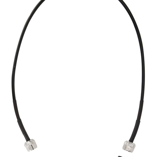


UT-W02-6GHz N-SMA RF Cable
109 In Stock
N-SMA-JJ RF cable,DC-6GHz VSWR≤1.25:1@6GHz IL≤1.8dB@6GHz
$55.00
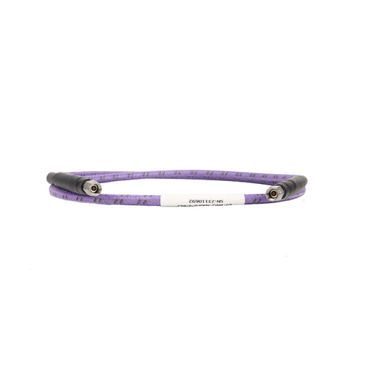

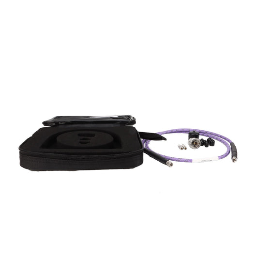
UT-W03-40GHz RF Cable
110 In Stock
2.92J-2.92J RF cable,DC-40GHz VSWR≤1.25:1@40GHz IL≤3.5dB@40GHz
$339.00
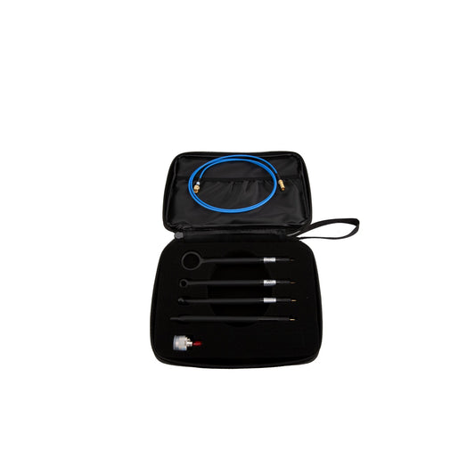

UTS-EMI01 Near-Field Probe Kit
59 In Stock
Kit includes 4 Pcs magnetic field near-field probes; 1 Pcs SMA-SMB cable, 1 Pcs Adapter SMA-N-KJ-T, 30MHz – 3GHz
$429.00