


UNI-T UDP5800-6 1200W Programmable DC Switching Power Supply (800V, 6A)
Overview
The UNI-T UDP5800-6 is a single-channel 1200W programmable DC switching power supply delivering 0.5–800 V and 0–6A with auto-ranging across the rated power envelope. It brings the same platform-level accuracy, source-emulation capability, and SCPI remote control as the rest of the UDP5000 family to high-voltage applications — 400 V and 800 V EV traction batteries, high-string PV, industrial DC bus — that lower-voltage tiers cannot reach.
Voltage accuracy is ±(0.05% of set + 0.05% of rated) and current accuracy ±(0.5% of set + 0.1% of rated); voltage ripple is held to 200mV p-p with a 100 ppm/°C temperature coefficient. A 2.4-inch TFT-LCD shows voltage, current and power together, and full SCPI control over USB and LAN drops the UDP5800-6 straight into LabVIEW, Python-VISA or any ATE framework.
Choosing Your Model — UDP5000 Series
The UDP5000 name spans 20 models built on one platform: five voltage classes (40 V / 80 V / 160 V / 250 V / 800 V) across four power classes (400 W / 800 W / 1200 W / 2000 W). They differ only in output range and chassis size — control, accuracy, protection and interface are otherwise identical. Compare the full series before selecting:
| Rated Power | 40 V | 80 V | 160 V | 250 V | 800 V |
|---|---|---|---|---|---|
| 400W |
UDP5040-40 0–40A |
UDP5080-20 0–20A |
UDP5160-8 0–8A |
UDP5250-6 0–6A |
UDP5800-2 0–2A |
| 800W |
UDP5040-80 0–80A |
UDP5080-40 0–40A |
UDP5160-16 0–16A |
UDP5250-12 0–12A |
UDP5800-4 0–4A |
| 1200W |
UDP5040-120 0–120A |
UDP5080-60 0–60A |
UDP5160-24 0–24A |
UDP5250-18 0–18A |
UDP5800-6 0–6A |
| 2000W |
UDP5040-200 0–200A |
UDP5080-100 0–100A |
UDP5160-40 0–40A |
UDP5250-30 0–30A |
UDP5800-10 0–10A |
Every model shares the same chassis architecture, control system, regulation accuracy, protection suite, and interface set. The 800 V UDP5800 tier does not support series connection; all other tiers support series and parallel combining. Choose by the voltage class that covers your rail and the power class that covers your load — output range and chassis height scale with power, the instrument does not change.
Key Features
- 1200W / 0.5–800 V / 0–6A — auto-ranging across the rated power envelope
- Voltage accuracy ±(0.05% of set + 0.05% of rated); current accuracy ±(0.5% of set + 0.1% of rated)
- Low ripple — 200mV p-p voltage, 18mA rms current (20 MHz BW)
- CC/CV priority slope modes — choose voltage-first or current-first turn-on for DUT safety
- Adjustable internal resistance to 100Ω — emulate high-voltage source impedance
- List Mode — 128 programmable V/I/dwell steps, 1 to 9,999 or infinite cycles, stand-alone
- Front and rear output terminals (front limited to 10 A)
- Multi-unit parallel only — 4 units maximum; series connection not supported at 800 V
- USB + LAN with full SCPI 1999.0 / IEEE-488.2; 2.4-inch TFT-LCD
- Discharge-load control for rapid output bleed-down; enhanced isolation — 1900 VAC withstand
UNI-T UDP5800-6 Details

CC/CV Priority — Protect the Device, Not Just the Supply
Most bench supplies treat the CC/CV crossover as a fixed hardware behaviour. The UDP5000 lets you choose which parameter takes priority at turn-on and during mode transitions. CV-priority establishes the target voltage first — the right choice for capacitor banks, converter input rails, and battery packs where voltage overshoot must be bounded. CC-priority brings current up under control — the right choice for electrolysis cells, formation rigs, and any load where inrush must be limited at 800 V.
CC/CV priority mode transition behaviour
Adjustable Slew Rate — Control How Fast Power Arrives
Voltage and current slew rates are independently settable. At 800 V, a controlled ramp is not optional — capacitive DUTs, battery packs, and film capacitors under formation all need current and voltage to arrive at a rate the load can absorb safely. High-speed mode is available when fast settling is the test requirement.
 Adjustable voltage and current slew rate

Internal Resistance — Simulate High-Voltage Source Impedance
The internal variable-resistance function (set in CV mode, up to 100Ω in 1 mΩ steps) makes the terminal voltage droop with load current exactly as a high-voltage battery pack or fuel cell stack would — no external resistor, no thermal risk at 800 V, value changeable instantly from the panel or over SCPI.
Internal variable resistance source emulation
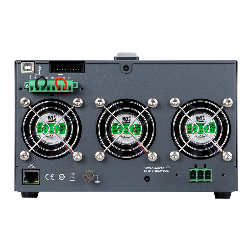
Front & Rear Outputs — Bench-Ready and Rack-Ready
Output terminals are provided on both panels. Front terminals are available for quick hookup; rear terminals keep permanent rack wiring clean and away from the high-voltage output when mounted in a test rack. Both share the same output — front-panel draw is limited to 10 A, so high-current loads belong on the rear.
 Front and rear output terminals

List Mode & Discharge Control — Automate Output Sequences
List Mode runs up to 128 programmed V/I/dwell steps for 1 to 9,999 or infinite cycles, stored locally or exported, executing with no PC attached — built for overnight formation runs, pack ageing cycles, and unattended production routines at 800 V. The internal discharge load bleeds output capacitance down rapidly when output is switched off.
List Mode programmable output sequencing
Multi-Unit Parallel — Scale Current When You Need More
Up to 4 identical units combine in parallel for proportionally higher output current, coordinated over the rear CAN / LS_BUS interface from the master unit or a single SCPI connection; unit-to-unit current balance stays within ~5% of rated. Series connection is not supported on the UDP5800 at 800 V.
 Multi-unit parallel operation

Display and Control
A 2.4-inch TFT-LCD presents voltage, current and power simultaneously with a concise multifunction keypad; external analog control (0–10 V setpoint plus digital ON/OFF) is available on the rear analog interface for closed-loop and HIL setups operating at high voltage.
UDP5000 front panel — 2.4-inch TFT-LCD with multifunction keypad
Applications
EV Traction Pack Formation
1200 W at 800 V supports pack-level formation cycling where constant-power behaviour tracks the rising cell voltage during charge without interruption.
High-String PV Test
Covers residential and commercial PV string open-circuit voltages up to 840 V for inverter MPPT testing, safety relay validation, and grid-tie qualification.
High-Voltage Motor Drive Test
Supplies the DC link of 800 V-class variable-frequency drives and traction inverters for efficiency and protection characterisation.
Accessories and Family Options
In the box: power cord (destination-country standard, 1.8 m), four-conductor analog-interface flat cable (3.5 m), USB cable (1.5 m), M3 mounting screws, output-terminal protection cover, and rack distribution bracket.
The UDP5000 series spans 20 models on one platform — see Choosing Your Model above for the full voltage × power matrix if a different rail or load fits your application better.
Frequently Asked Questions
Can I use the front and rear output terminals at the same time?
Both terminal sets are parallel connections to the same single output. You can wire both, but the front terminals are limited to 10 A maximum — route high-current loads to the rear panel.
What is the difference between the VHS/IHS and VSR/ISR slope modes?
VHS (CV high-speed) and IHS (CC high-speed) use the supply's default fast rise and fall rates. VSR (CV slope) and ISR (CC slope) let you set the rise and fall rate so output ramps in controlled fashion — at 800 V this is critical for capacitive and battery loads that cannot absorb uncontrolled current at turn-on.
Does the internal-resistance function need an external resistor?
No. The internal variable-resistance function electronically emulates source impedance (set in CV mode, up to 100Ω in 1 mΩ steps), so the supply behaves like a high-voltage battery pack or fuel cell stack with no physical resistor and no added thermal risk.
Can multiple units be combined for more power?
Yes, up to 4 identical units in parallel for more current, coordinated from the master unit or a single SCPI connection; unit-to-unit balance stays within ~5% of rated. Series connection is not supported on the UDP5800 — the 800 V output already reaches the system ceiling for this platform.
How does it integrate with automated test?
USB and LAN with full SCPI 1999.0 / IEEE-488.2 support LabVIEW, Python-VISA and any standard ATE framework; List Mode runs stored sequences stand-alone without a connected PC.
| DC Voltage Out | 800 V |
| DC Current Out | 6 A |
| DC Power Out | 1200 W |
| Voltage Resolution | 1 mV (< 100 V) / 10 mV (≥ 100 V) |
| Current Resolution | 1 mA |
| Programmable | Yes |
| Channels | 1Ch |
| Interface | USB-Device, USB-Host, LAN, Analog I/O |
| Certifications | CE |
| Country of Origin | China |
Data Sheets and Manuals
Software / Firmware Downloads
- Not currently available. Contact us with questions.