


UNI-T UDP5160-8 400W Programmable DC Switching Power Supply (160V, 8A)
Overview
The UNI-T UDP5160-8 is a single-channel 400W programmable DC switching power supply delivering 0–160V and 0–8A with auto-ranging across the rated power envelope. It pairs a wide output range with the regulation accuracy, source-emulation and remote control expected of a professional programmable supply.
Voltage accuracy is ±(0.05% of set + 0.05% of rated) and current accuracy ±(0.5% of set + 0.1% of rated); ripple is held to 100mV p-p with a 100 ppm/°C temperature coefficient. A 2.4-inch TFT-LCD shows voltage, current and power together, and full SCPI control over USB and LAN drops the UDP5160-8 straight into LabVIEW, Python-VISA or any ATE framework.
Choosing Your Model — UDP5000 Series
The UDP5000 name spans 20 models built on one platform: five voltage classes (40 V / 80 V / 160 V / 250 V / 800 V) across four power classes (400 W / 800 W / 1200 W / 2000 W). They differ only in output range and chassis size — control, accuracy, protection and interface are otherwise identical. Compare the full series before selecting:
| Rated Power | 40 V | 80 V | 160 V | 250 V | 800 V |
|---|---|---|---|---|---|
| 400W |
UDP5040-40 0–40A |
UDP5080-20 0–20A |
UDP5160-8 0–8A |
UDP5250-6 0–6A |
UDP5800-2 0–2A |
| 800W |
UDP5040-80 0–80A |
UDP5080-40 0–40A |
UDP5160-16 0–16A |
UDP5250-12 0–12A |
UDP5800-4 0–4A |
| 1200W |
UDP5040-120 0–120A |
UDP5080-60 0–60A |
UDP5160-24 0–24A |
UDP5250-18 0–18A |
UDP5800-6 0–6A |
| 2000W |
UDP5040-200 0–200A |
UDP5080-100 0–100A |
UDP5160-40 0–40A |
UDP5250-30 0–30A |
UDP5800-10 0–10A |
Every model shares the same chassis architecture, control system, regulation accuracy, protection suite, and interface set. The 800 V UDP5800 tier does not support series connection; all other tiers support series and parallel combining. Choose by the voltage class that covers your rail and the power class that covers your load — output range and chassis height scale with power, the instrument does not change.
Key Features
- 400W / 0–160V / 0–8A — auto-ranging across the rated power envelope
- Voltage accuracy ±(0.05% of set + 0.05% of rated); current accuracy ±(0.5% of set + 0.1% of rated)
- Low ripple — 100mV p-p voltage, 30mA rms current (20 MHz BW)
- CC/CV priority slope modes — choose voltage-first or current-first turn-on for DUT safety
- Adjustable internal resistance to 15Ω — emulate batteries, fuel cells and solar sources
- List Mode — 128 programmable V/I/dwell steps, 1 to 9,999, infinite cycles, stand-alone
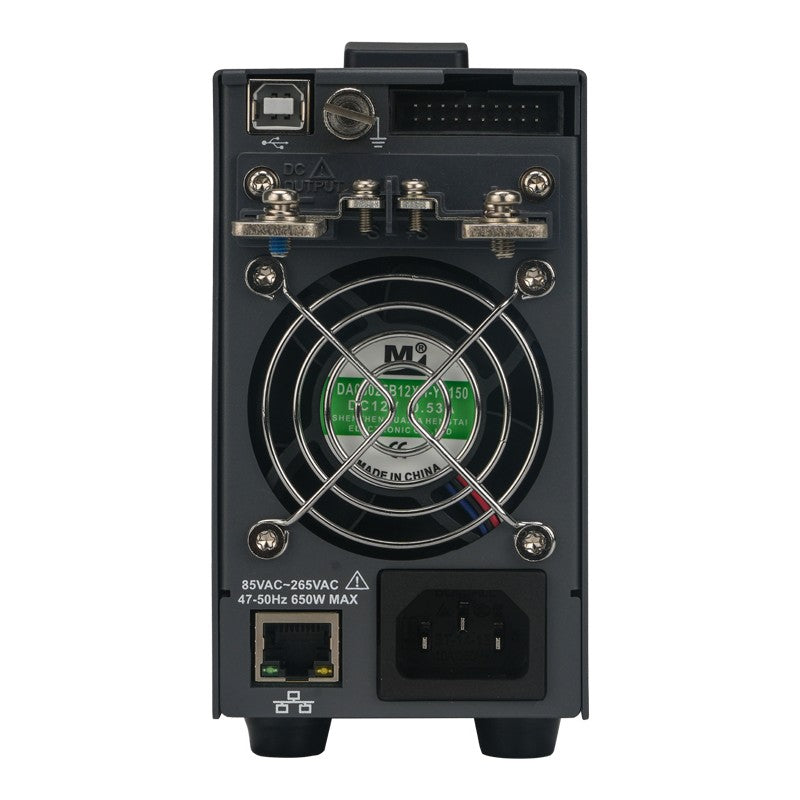
- Front and rear output terminals (front limited to 10 A)
- Multi-unit series/parallel — up to 4 parallel / 2 series
- USB + LAN with full SCPI 1999.0 / IEEE-488.2; 2.4-inch TFT-LCD
- Discharge-load control for rapid output bleed-down
UNI-T UDP5160-8 Details

CC/CV Priority — Protect the Device, Not Just the Supply
Most bench supplies treat the CC/CV crossover as a fixed hardware behaviour. The UDP5000 lets you choose which parameter takes priority at turn-on and during mode transitions. CV-priority establishes the target voltage first — the right choice for microcontrollers, FPGAs and analog rails. CC-priority brings current up under control — the safer choice for LEDs, laser diodes and battery charging where inrush must be bounded.
CC/CV priority mode transition behaviour
Adjustable Slew Rate — Control How Fast Power Arrives
Voltage and current slew rates are independently settable. A slower ramp prevents inrush into capacitive loads, reduces mechanical stress on motor windings at start-up and gives sensitive analog circuits time to settle; the high-speed default mode is there when fast settling is what the test needs.
 Adjustable voltage and current slew rate

Internal Resistance — Simulate Real Power Sources
The internal variable-resistance function (set in CV mode, up to 15Ω in 1 mΩ steps) makes the terminal voltage droop with load current exactly as a battery, fuel cell or solar panel would — no physical resistor, no thermal risk, value changeable instantly from the panel or over SCPI.
Internal variable resistance source emulation
Front & Rear Outputs — Bench-Ready and Rack-Ready
Output terminals are provided on both panels. Front terminals are there for quick prototype hookup; rear terminals keep permanent rack wiring clean. Both are the same single output — front-panel draw is limited to 10 A, so high-current loads belong on the rear.
 Front and rear output terminals

List Mode & Discharge Control — Automate Output Sequences
List Mode runs up to 128 programmed V/I/dwell steps for 1 to 9,999, infinite cycles or continuously, stored locally or exported, executing with no PC attached — built for overnight burn-in, charge-profile runs and production routines. The internal discharge load bleeds output capacitance down rapidly when output is switched off.
List Mode programmable output sequencing
Multi-Unit Operation — Scale When You Need More
Up to 4 identical units parallel for more current, or up to 2 in series for more voltage, coordinated over the rear CAN / LS_BUS interface from the master unit or a single SCPI connection; unit-to-unit balance stays within ~5% of rated.
 Multi-unit series and parallel operation

Display and Control
A 2.4-inch TFT-LCD presents voltage, current and power simultaneously with a concise multifunction keypad; external analog control (0–10 V setpoint plus digital ON/OFF) is available on the rear analog interface for closed-loop and HIL setups.
UDP5000 front panel — 2.4-inch TFT-LCD with multifunction keypad
Applications
Power-Electronics and SiC Development
0–160 V suits SiC half-bridge, PFC front-end and industrial three-phase intermediate-bus work where a stiff, low-ripple programmable rail is needed.
EV-Charging and Industrial Subsystems
Internal-resistance emulation reproduces real source impedance for charger and converter validation; protection delay and OVP/OCP guard the DUT.
Automated Test and Production
SCPI over USB or LAN plus stored List Mode sequences make the UDP5000 a clean fit for unattended characterisation, burn-in and end-of-line test.
In the Box
- UDP5160-8 DC power supply
- Power cord (region-appropriate)
- USB 2.0 cable, 1.5 m (USB-A to USB-B)
- 4-way ribbon cable (3 x 350 mm, 2 x 10-pin)
- Output protection cover (upper and lower shell, one M3 cross-head screw)
- Distribution rack
- Factory calibration certificate
- Quick-start guide
Accessories and Family Options
In the box: power cord (destination-country standard, 1.8 m), four-conductor analog-interface flat cable (3.5 m), USB cable (1.5 m), M3 mounting screws, output-terminal protection cover, and rack distribution bracket.
The UDP5000 series spans 20 models on one platform — see Choosing Your Model above for the full voltage × power matrix if a different rail or load fits your application better.
Frequently Asked Questions
Can I use the front and rear output terminals at the same time?
Both terminal sets are parallel connections to the same single output. You can wire both, but the front terminals are limited to 10 A maximum — route high-current loads to the rear panel.
What is the difference between the VHS/IHS and VSR/ISR slope modes?
VHS (CV high-speed) and IHS (CC high-speed) use the supply's default fast rise and fall rates. VSR (CV slope) and ISR (CC slope) let you set the rise and fall rate so output ramps in controlled fashion — useful for capacitive and motor loads, and for sensitive analog circuits that need settling time.
Does the internal-resistance function need an external resistor?
No. The internal variable-resistance function electronically emulates source impedance (set in CV mode, up to 15Ω in 1 mΩ steps), so the supply behaves like a battery, fuel cell or solar source with no physical resistor and no added thermal risk.
Can multiple units be combined for more power?
Yes. Identical models combine for more current (parallel, up to 4 units) or more voltage (series, up to 2 units), controlled from the master unit or a single SCPI connection; unit-to-unit balance stays within ~5% of rated.
How does it integrate with automated test?
USB and LAN with full SCPI 1999.0 / IEEE-488.2 support LabVIEW, Python-VISA and any standard ATE framework; List Mode runs stored sequences stand-alone without a connected PC.
Warranty
This instrument is backed by UNI-T's 3+2 Year Warranty — 3 years of standard coverage, plus 2 additional years free when you register your product. That's 5 years of total protection at no extra cost.
The warranty covers manufacturing defects and component failures under normal use conditions. UNI-T instruments are built for professional daily use, and our warranty reflects that commitment to long-term reliability.
| Output Voltage | 160 V |
|---|---|
| Output Current | 8 A |
| Total Output Power | 400 W |
| Channels | 1Ch |
| Voltage Resolution | 1mV (<100V) / 10mV (≥100V) |
| Programmable | ✓ |
| Instrument Type | DC Switching PSU |
| Supply Type | DC Switching |
Features
Full specifications (23)
| Details | |||||||||||
|---|---|---|---|---|---|---|---|---|---|---|---|
| Current Resolution | 1mA | ||||||||||
| Max. Adjustable Voltage | 168 V | ||||||||||
| Max. Adjustable Current | 8.4 A | ||||||||||
| Rise Time |
|
||||||||||
| Features | |||||||||||
| Line Regulation |
|
||||||||||
| Load Regulation |
|
||||||||||
| Ripple & Noise |
|
||||||||||
| Fall Time (rated load) |
|
||||||||||
| Setting Accuracy (25 °C ± 5 °C) |
|
||||||||||
| Setting Resolution |
|
||||||||||
| Overvoltage protection |
|
||||||||||
| Overcurrent protection |
|
||||||||||
| Max Parallel-Connected Units | Supports up to four parallel-connected units (same model), including the master unit. | ||||||||||
| Max Series-Connected Units | Except for the 5800 model, Supports up to two series-connected units (same model). | ||||||||||
| Adjustable Internal Resistance (max) | 15 Ω | ||||||||||
| General Information | |||||||||||
| Interface | USB-Device|LAN|Analog I/O | ||||||||||
| Dimensions (W×H×D) | 71 × 124 × 350 mm | ||||||||||
| Weight | 3 kg | ||||||||||
| Warranty | 3+2 years | ||||||||||
| Certifications | CE | ||||||||||
| Storage | Group Number: 32×3 groups | ||||||||||
| Over-temperature protection | Automatically turns off*1 when triggered, and a window display: "OTP is triggered, the output will be turned off." | ||||||||||
| Remote Sense Compensation (max) | 5 V | ||||||||||
Data Sheets and Manuals
Authentic UNI-T accessories are an affordable way to extend the functionality of your instrument.


Interactive guides for this power supply
DC power supplies · Battery emulation
Make your bench supply sag like a real battery
A bench supply set to 14.8 V delivers 14.8 V at 1 A and at 10 A. The battery pack it stands in for does not. Its voltage drops as the current rises, and the firmware that watches for low voltage only ever sees that drop on the real pack.
Yellow: a supply with no internal resistance. Blue: the same supply with the resistance you set. Red dashes: your device's undervoltage cutoff. The dots sit at the load current you choose.
Why a stiff rail hides problems
Every battery has internal resistance. Pull current from it and part of the voltage is lost inside the battery, so the terminal voltage is the open-circuit voltage minus current times resistance. A 4S lithium-ion pack with 0.15 Ω loses 1.5 V at 10 A before your circuit gets any of it.
That drop is what a lot of firmware is written to handle. Undervoltage lockout, low-battery warnings, motor current limits that back off as the pack sags, DC-DC converters that have to stay stable with a soft input: none of it is exercised on a supply that holds 14.8 V no matter what. The first time it runs for real is on a customer's battery.
Why a resistor in series is a poor fix
The usual workaround is a power resistor between the supply and the device. It does sag the voltage, but it has a fixed value, it gets hot (I² × R, shown in the last readout), and its resistance drifts as it heats. Changing the value means changing the part.
A UDP5000 does the same job in its control loop. You enter a resistance and the supply lowers its own output by I × R as the load current changes. Nothing on the bench gets hot, and the value changes from the front panel or over SCPI.
What the UDP5000 can set
The internal resistance works in constant-voltage mode and sets in 0.001 Ω steps on every model. The maximum depends on the model: rated voltage divided by rated current on the 40 V and 80 V models, and three quarters of that on the 160 V, 250 V and 800 V models.
| 400 W model | Rated output | Maximum internal resistance |
|---|---|---|
| UDP5040-40 | 40 V / 40 A | 1.000 Ω |
| UDP5080-20 | 80 V / 20 A | 4.000 Ω |
| UDP5160-8 | 160 V / 8 A | 15 Ω |
| UDP5250-6 | 250 V / 6 A | 31.25 Ω |
| UDP5800-2 | 800 V / 2 A | 300 Ω |
From the UDP5000 data sheet. The other 15 models are in the picker above.
Try this
- Pick the 4S pack and set the load to 10 A. The device sees 13.30 V, comfortably above a 12.0 V cutoff. Push the load past 18.7 A and the cutoff fires, even though the stiff supply still shows 14.8 V.
- Set the internal resistance to zero. The blue line lies on the yellow one, and the cutoff never fires at any current the supply can deliver.
- Pick the 13S pack on the UDP5040-40. Its 48.1 V is above what a 40 V model can output, so switch the supply to the UDP5080-20.
This is a resistance, not a full battery model. The supply holds the open-circuit voltage you set, so it does not discharge the way a battery does over minutes, and it does not copy the slower voltage recovery a cell shows after a load step. For testing cutoffs, warnings and converter stability at a known source resistance, it is the part that matters.
Battery values in the presets are typical figures for illustration. Measure your own pack, or take its internal resistance from the cell maker's data sheet.
Read this as an article, with room to share it.
Open the full articleRelated: UNI-T's white paper on adjustable internal resistance · Constant voltage vs. constant current. UNI-T. Design. Debug. Deploy.™
DC power supplies · Output range
Why one 400 W supply can be 40 V at 10 A or 10 V at 40 A
Two supplies can both be called 400 W and still cover very different jobs. One gives you its full current only up to a fixed voltage. The other trades voltage for current along its power limit, so the same box runs a 36 V motor driver in the morning and a 5 V FPGA board in the afternoon.
Shaded blue: everything the UDP5000 model can deliver. Yellow and pink outlines: two fixed-range supplies with the same power rating. The dot is your test point.
A rectangle or a curve
A fixed-range supply has a maximum voltage and a maximum current, and its rated power is their product. A 400 W fixed-range supply might be 40 V and 10 A. Every point inside that rectangle works. A 5 V load that needs 30 A does not, even though it only asks for 150 W.
A wide-range supply has a larger voltage limit and a larger current limit, and its output is held under the rated power by the control loop. The operating area is bounded by the power curve, V × I = P, between the two limits. The UDP5040-40 reaches 40 V or 40 A, at up to 400 W in any combination.
A fixed-range supply has a power ratio of 1. Every UDP5000 model has a ratio of 4: 40 V × 40 A ÷ 400 W on the UDP5040-40, and 800 V × 2 A ÷ 400 W on the UDP5800-2. To cover the same corners with fixed-range supplies you would need a 1,600 W unit, or two smaller supplies on the bench.
What you give up
You cannot have full voltage and full current at the same time. At 40 V the UDP5040-40 delivers 10 A, the same as the fixed-range unit. The gain is everywhere else on the curve. If your work really is one fixed point at full voltage and full current, size the supply for that point.
The front binding posts carry up to 10 A. Above that, wire the load to the rear output terminals.
Try this
- On the UDP5040-40, press Middle: 12 V at 30 A, a 12 V automotive module on the bench. The UDP5000 covers it at 360 W. The 40 V / 10 A fixed-range supply runs out of current, and the 10 V / 40 A one runs out of voltage.
- Press High voltage, then High current. The first point fits only the full-voltage rectangle and the second only the full-current one. The shaded area covers both.
- Switch the model to the UDP5250-6 and press Middle. The curve has the same shape at a higher voltage: 250 V or 6 A, up to 400 W.
Read this as an article, with room to share it.
Open the full articleRelated: Constant voltage vs. constant current · Linear vs. switching supplies. UNI-T. Design. Debug. Deploy.™
DC power supplies · Start-up behavior
Where LED current overshoot comes from, and how CC priority stops it
Set a bench supply to 350 mA, switch it on into an LED string, and the meter settles at 350 mA. What the meter does not show is the first few milliseconds, when the current can run several times higher before the current limit takes control.
Yellow: output voltage. Blue: current through the LED string. Red dashes: the current you set. Illustrative model, not a measurement of a UDP5000.
Why the spike happens
With constant-voltage priority, the supply's voltage loop is in charge at switch-on. It drives the output toward the voltage setting as fast as it can. An LED string draws almost nothing until the voltage reaches its forward voltage, then the current climbs steeply, because the string's resistance above that point is small. By the time the current loop sees too much current and takes over, the output is already well above the voltage the string needs at 350 mA.
The excess lasts a few milliseconds. LEDs and laser diodes carry a peak-current rating, and a spike like this can go past it on every power-up. Setting the voltage only slightly above the string helps, but it leaves no margin as the string warms and its forward voltage drops.
Two ways to remove it
CC priority. Here the current loop is in charge from the start. Voltage rises only as far as it takes to reach the current setting, so the current comes up to 350 mA and stays there. On the UDP5000 this is IHS (high-speed) or ISR (with a set slope).
A slower voltage slope. In CV slope priority (VSR) the voltage ramps at the rate you set. The current still crosses the limit, but slowly enough that the current loop catches it with a small overshoot.
Both are front-panel settings on the UDP5000, and both are available over SCPI with the :OUTPut:MODE command.
Pick a model for the current, not only the power
LED strings draw little current. The data sheet gives current ripple in CC mode, and it is lowest on the high-voltage, low-current models: 6 mA rms on the UDP5800-2 and 12 mA rms on the UDP5250-6, against 80 mA rms on the UDP5040-40. For a 350 mA string, choose the model whose voltage covers the string and whose current is closest to what you need.
Try this
- With CV priority, 8 LEDs and 350 mA, the current peaks well above the red line before it settles.
- Press CC priority. The current rises to the setting and stops there.
- Press CV, slope and drag the slope down. The spike shrinks as the ramp gets slower.
The traces come from a simple model: white LEDs at 3.0 V each with 0.5 Ω of dynamic resistance, a voltage loop that settles in about a millisecond, and a current loop that reacts about a millisecond after the current crosses its limit. Real numbers depend on the LEDs, the wiring and the supply. To see your own start-up, put a current probe on the LED lead and trigger a scope on the output switching on.
Read this as an article, with room to share it.
Open the full articleRelated: Constant voltage vs. constant current. UNI-T. Design. Debug. Deploy.™
DC power supplies · Multi-unit operation
Two supplies or four: what series and parallel operation give you
When a test outgrows one supply, the choice is a bigger supply or a second identical one. Linked UDP5000 units act as one: you set the master, the others follow, and the output adds up in current (parallel) or in voltage (series).
Red is positive, grey is negative. The grey ribbon is the link cable between the units' rear interface ports. Numbers show what each unit carries at the load you set.
Parallel adds current
In parallel, the positive terminals join and the negative terminals join, and the load sits across them. Each unit holds the same voltage and the currents add. Four UDP5080-20 units give 80 V at up to 80 A and 1,600 W.
Up to four units link on the 400 W, 800 W and 1,200 W models, and two on the 2,000 W models. Combined output is capped at 5,000 W, so the largest group is four 1,200 W units at 4,800 W.
Series adds voltage
In series, the positive terminal of the first unit connects to the negative terminal of the second, and the load sits across the outer two. The voltages add and the current is the rating of one unit. Two UDP5250-6 units reach 500 V at 6 A. Series operation is limited to two units, and the 800 V models run in parallel only.
How the units share the work
The units are linked by a ribbon cable on the rear interface port. On each unit you choose its role in the menu: master, or slave with an ID. After that you set voltage and current on the master only, and the slaves follow it. The data sheet allows up to about 5 % of the rated value of difference between master and slave, so in a four-unit UDP5080-20 group each unit carries 20 A ± 1 A at full load.
Wire the load to the rear output terminals. The front binding posts are limited to 10 A per unit.
Check the outlets before you build the rack
Each unit draws its own AC input. The data sheet gives full-load input current at 100 V and at 200 V. A 2,000 W model draws 28 A at 100 V, more than a 120 V branch circuit is built for, so plan 208 V or 240 V circuits for those models. At 1,200 W the figure is 16.8 A at 100 V, which needs a dedicated 20 A circuit per unit on 120 V.
Try this
- Pick the UDP5080-20, Parallel, 4 units. The group reaches 80 A. Set a 50 A load and each unit carries 12.5 A.
- Switch to Series. The button for 3 and 4 units turns off, and the group reaches 160 V at 20 A.
- Pick a 2,000 W model. Parallel stops at 2 units, and the AC input line shows why the outlet matters.
Linked operation needs identical models. Ratings and limits are from the UDP5000 data sheet and UNI-T's confirmation of the parallel limits.
Read this as an article, with room to share it.
Open the full articleRelated: Series vs. parallel circuits. UNI-T. Design. Debug. Deploy.™
DC power supplies · Automated sequences
Burn-in and power cycling without a PC on the bench
Plenty of repetitive bench work needs no test software: hold a board at three voltages for an hour each, switch a product on and off a thousand times, step a load through a soak. A UDP5000 runs that kind of sequence by itself from a list stored in the supply.
One cycle of your list. Yellow: voltage setting. Blue dashes: current setting. Step lengths are drawn to scale.
| Step | Voltage (V) | Current (A) | Time (s) |
|---|
What the list holds
Each step is a voltage setting, a current setting and a time. The supply runs the steps in order, then repeats the whole list for the number of cycles you set, from 1 to 9,999, or until you stop it. A list can hold up to 128 steps, and each step can last from 0.1 s to 99,999.9 s, a little over 27 hours.
You can build the list on the front panel, in UNI-T's PC software, or in the supply's built-in web page over the network. A separate Delayer function switches the output on and off on a timed schedule, with times from 0.1 s to 9,999.9 s, for cycling that needs no voltage changes.
Three jobs it covers
Voltage margins. Run the product at its nominal input, then 5 % high, then 5 % low, and watch for resets or errors. Contract manufacturers use this on boards that will see a range of adapters and batteries in the field.
On/off cycling. Alternate a step at nominal voltage with a step at 0 V. Hundreds of cold starts find the board that fails to boot one time in fifty, a fault a single power-up will not show.
Step soak. Raise the voltage in stages and hold each one, so that a weak part shows up at a known point instead of at full stress.
When to move to a script
A list runs open loop. It does not read a measurement and decide what to do next, and it does not log results. When the test has to branch, stop on a failure, or record every reading, drive the supply over USB or LAN with SCPI commands from a script. The same supply does both, so a sequence can start as a list and move to a script later.
Try this
- Voltage margins at 12 V, three steps of 60 s and 60 cycles: the run takes 3 hours.
- Press On/off cycling and set 1,000 cycles. Each cycle is 40 s, so the run lasts about 11 hours.
- Type a step voltage above 105 % of the model's rating, for example 45 V on the UDP5040-40. The check flags it, because the setting range ends at 105 % of rated output.
Read this as an article, with room to share it.
Open the full articleUNI-T. Design. Debug. Deploy.™
DC power supplies · Capacitive loads
Inrush into capacitive loads: set the ramp instead of fighting it
A motor drive, an inverter or a DC-DC module often has thousands of microfarads across its input. Charging that capacitance takes current in proportion to how fast the voltage rises. Switch the supply on at full speed and the board sees a current spike. Ramp it at a rate you choose and the current is a number you set in advance.
Yellow: output voltage. Blue: current into the load. Red dashes: the supply's current setting. Purple dashes: the rating you enter for the board's input fuse or connector.
The current a capacitor asks for
A capacitor draws current only while its voltage is changing. The current is the capacitance times the rate of rise:
Take 4,700 µF and bring it to 24 V in 5 ms. The rate is 4,800 V/s and the current is 22.6 A, for a board that runs on 2 A. The same capacitor ramped over half a second needs 0.23 A.
What a fast start does
On a fast start, the supply's own speed sets the rate of rise. Either the current goes to the setting and the supply drops into constant current until the capacitor has charged, or, with a generous current setting, the board's input fuse, connector and precharge parts take the full spike. Neither tells you how the board behaves when it is powered the way the product will be.
Setting the ramp
The UDP5000's slope modes let you set how fast the output voltage rises and falls, in volts per second. UNI-T gives the range as 0.01 V/s to 500 V/s. With the rate fixed, the charging current is fixed too, and you can choose it: well under the fuse rating to bring a board up gently, or at a known value to check that a soft-start or precharge circuit works.
The supply's protection has its own delay. Over-voltage and over-current protection can wait from 10 ms to 10,000 ms before acting, so a short, expected peak does not shut the output down while a sustained fault still does.
Try this
- On the UDP5040-40 at 24 V with 4,700 µF, compare High speed with Set slope at 100 V/s. The charging current drops from at least 2.26 A to 0.47 A.
- On High speed, lower the current setting. The supply goes into current limit, and the ramp time grows to whatever that current allows.
- Raise the capacitance to 47,000 µF at 100 V/s. The charging current reaches 4.7 A, still a value you chose.
The High speed estimate uses the data sheet rise time at rated load (below 50 ms for the 40 V and 80 V models, 100 ms for 160 V and 250 V, 250 ms for 800 V) as the ramp. A real fast start can be quicker, so treat that figure as a lower bound on the spike. Board current after the capacitor has charged is not included.
Read this as an article, with room to share it.
Open the full articleRelated: Constant voltage vs. constant current. UNI-T. Design. Debug. Deploy.™