


MSO1254HD-S | 250 MHz 4Ch 12-Bit MSO with Signal Generator
Overview
The MSO1254HD-S is a 250 MHz, 4-channel, 12-bit Mixed Signal Oscilloscope built around UNI-T's native 12-bit ADC architecture (R12™) with an integrated 1-channel 25 MHz arbitrary waveform generator. It samples at 2.5 GSa/s with 100 Mpts of memory depth per channel and captures waveforms at 200,000 wfms/s, up to 1,000,000 wfms/s in Sequence Mode on a 7-inch capacitive touchscreen powered by Ultra Phosphor 3.0 acquisition technology.
Built for power-electronics validation and design verification in a single instrument, the 12-bit ADC delivers 4,096 vertical levels at the full 250 MHz bandwidth while a 1-channel 25 MHz arbitrary waveform generator drives the device under test from the same front panel. Bode plot analysis characterizes power-supply control loops and filter circuits without a second instrument on the bench. Standard protocol decoding covers the full embedded-systems vocabulary (RS-232, UART, I²C, SPI, RS-422, RS-485, CAN, CAN-FD, LIN, and Audio) at no additional cost.
The 9-in-1 architecture consolidates oscilloscope, logic analyzer (with optional UT-M26 pod), spectrum analyzer, protocol analyzer, digital voltmeter, frequency counter, AWG, Bode plotter, and power analyzer into one instrument.
Key Features
- 250 MHz Bandwidth, 4 Analog Channels — Four-channel acquisition at 12-bit native resolution for mixed-signal debugging, switching-power analysis, and precision sensor work.
- R12™ — Native 12-Bit ADC at Full Bandwidth — 4,096 vertical levels at every supported bandwidth — no ERES averaging, no sample-rate trade.
- 2.5 GSa/s Sample Rate, 100 Mpts/Channel — Captures fast edges with sufficient timing resolution and holds long records without dropping sample rate.
- 200,000 wfms/s Capture Rate — 1,000,000 wfms/s in Sequence Mode — Ultra Phosphor 3.0 intensity-graded display reveals rare anomalies and timing violations that slower scopes miss.
- 16 Optional Digital Channels — Add mixed-signal debugging with the UT-M26 logic probe pod for time-correlated analog and digital views.
- All Protocol Decoding Standard — RS-232/UART, I²C, SPI, RS-422, RS-485, CAN, CAN-FD, LIN, and Audio decoding included at no additional cost.
- Built-In 25 MHz Arbitrary Waveform Generator — 1-channel AWG output for stimulus-response testing without a separate signal generator on the bench.
- Bode Plot Analysis — Automated frequency response sweeps drive power-supply loop characterization and filter rolloff measurement.
- Built-In Spectrum Analyzer — FFT analysis up to 1 Mpts with peak detection and markers for harmonics, clock spurs, and EMI investigation.
- 56 Automated Measurements — Time, voltage, frequency, and power-quality parameters with statistical analysis and trend graphs.
- Built-In Power Analysis — 12 power-quality parameters including efficiency, ripple, and switching loss for switching-supply characterization.
- 7-Inch Capacitive Touchscreen — 1024×600 multi-gesture display with pinch-to-zoom, drag, and gesture navigation.
- Lab-Friendly Connectivity — USB Host/Device, LAN, AUX Out, HDMI, and Generator Out (-S models).
R12™ — Native 12-Bit ADC at Full Bandwidth
R12™ is UNI-T's native 12-bit ADC architecture. It samples at 4,096 quantization levels — sixteen times the vertical detail of a conventional 8-bit oscilloscope — and holds that resolution at the full 250 MHz bandwidth and 2.5 GSa/s sample rate. There's no ERES averaging step, no sample-rate trade, and no asterisk on the spec sheet.
For power-electronics validation at full bandwidth, R12 is what lets the MSO1254HD-S characterize a GaN/SiC half-bridge in the same bench session as the gate-drive ringing analysis. On a switching-node measurement where 8-bit quantization noise would obscure the µV-scale ripple riding on a 400 V rail, the 12-bit resolution recovers the signal that drives design decisions.
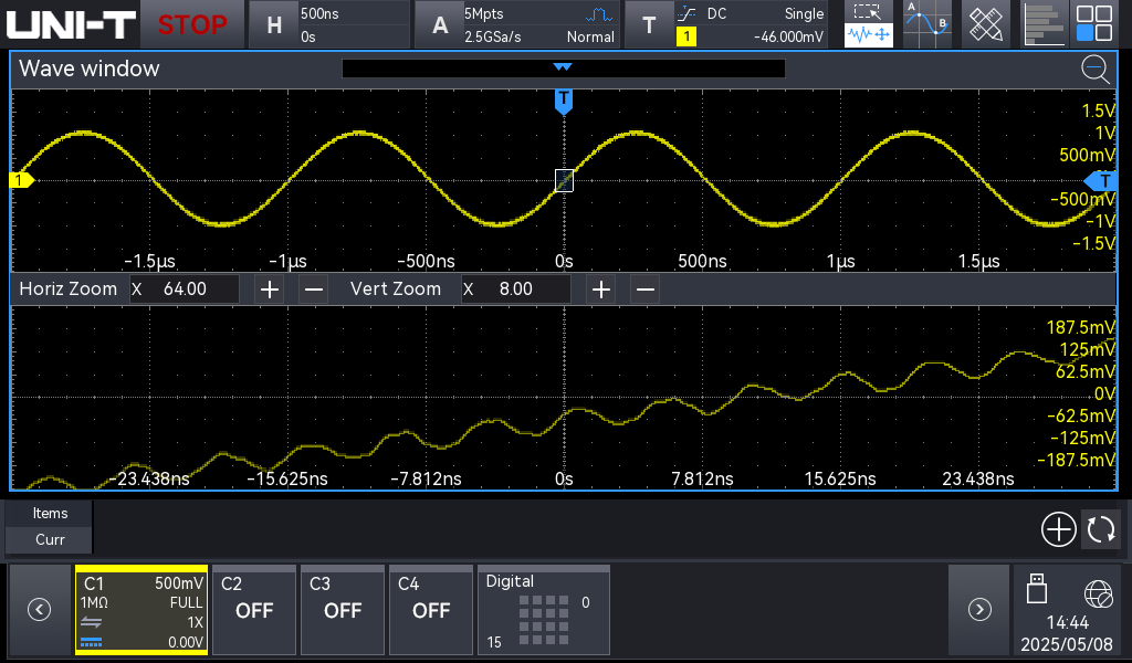 Native 12-bit ADC delivers 4,096 vertical levels at full bandwidth
Ultra Phosphor 3.0 — 200,000 wfms/s Acquisition, 1,000,000 wfms/s in Sequence Mode
Ultra Phosphor 3.0 drives the acquisition system at up to 200,000 waveforms per second, rising to 1,000,000 in Sequence Mode, with 256 levels of color intensity mapping. The intensity-graded display shows you signal behavior patterns that a slower scope flattens into solid traces — rare glitches, edge jitter, and occasional protocol-layer anomalies appear as faint trace markings against the dominant signal.
For intermittent-fault investigation, this is the difference between catching the event in a two-minute capture and waiting for it across an overnight run. The probability of capturing rare anomalies scales with capture rate; one million waveforms per second puts you in the territory where most timing violations show up before lunch.
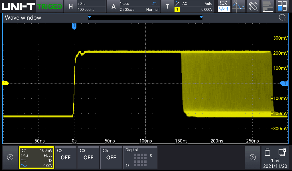 Ultra Phosphor 3.0 reveals rare events with intensity grading
Deep Memory — 100 Mpts Per Channel
100 Mpts of memory depth per channel maintains the full 2.5 GSa/s sample rate across wide time-base settings. You can capture an entire CAN-FD packet sequence, an extended power-on transient, or a long servo control loop without aliasing or missing events. Zoom into any portion of the captured record at full resolution.
Combined with the 1,000,000 wfms/s Sequence Mode capture rate, deep memory makes long-record analysis practical for bench debugging — one acquisition can replace a multi-pass capture campaign.
All Protocols Included Standard
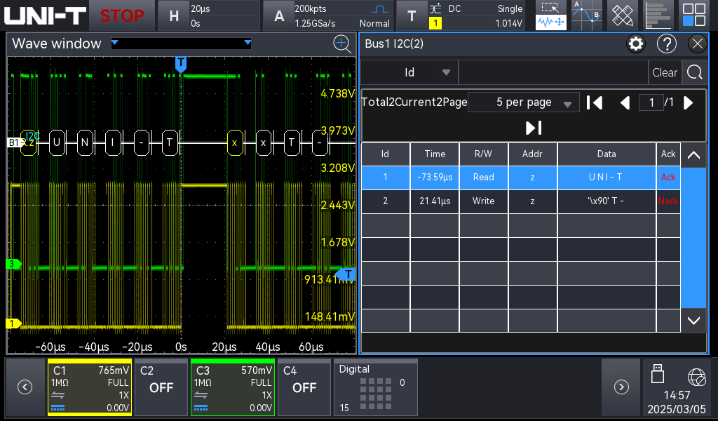
Unlike higher-tier families that charge separately for automotive and industrial protocols, the MSO1000HD platform includes RS-232/UART, I²C, SPI, RS-422, RS-485, CAN, CAN-FD, LIN, and Audio decoding standard at no additional cost. This makes it one of the most complete embedded-debug platforms in its segment, with no surprise license invoices when an automotive project crosses your bench.
Each decoder correlates the physical-layer signal with the decoded data above the trace, so you can see signal-integrity anomalies and protocol errors in the same acquisition. Search and trigger on data patterns, error conditions, or specific bus events to isolate intermittent communication faults.
Comprehensive protocol decoding included standard
Built-In AWG and Bode Plot Analysis
The integrated 1-channel 25 MHz arbitrary waveform generator outputs sine, square, ramp, pulse, noise, and user-defined arbitrary waveforms directly from the MSO1254HD-S's front panel. For closed-loop testing on power-supply controllers, motor drives, and sensor conditioning circuits, the AWG eliminates a second instrument from the bench — drive the device under test and capture the response on the same time axis.
The Bode plot function sweeps the AWG across a frequency range while measuring gain and phase on the input channel. The result is a frequency-response plot for power-supply control-loop characterization, filter rolloff verification, and amplifier bandwidth measurement — the workflow that normally requires a dedicated network analyzer is now a function on the same instrument that captured the switching waveform.
Built-In Power Analysis — 12 Parameters
12 standard power-quality parameters cover efficiency analysis, switching-loss measurement, safe-operating-area visualization, ripple-and-noise characterization, and harmonic content. The measurements run inline on the captured waveform — no scripting, no external software, no PC connection required.
Combined with the 12-bit ADC and 100 Mpts memory, the power-analysis suite handles workloads that previously required a dedicated power analyzer. For switching-supply validation, gate-drive characterization, and small-signal-on-DC-rail measurements, the integrated functions consolidate a multi-instrument workflow into one bench unit.
Built-In Spectrum Analyzer — FFT to 1 Mpts
Frequency-domain analysis with peak detection, markers, and waterfall display — up to 1 Mpts FFT length. Identify harmonics, clock spurs, switching-frequency content, and EMI contributions without switching to a separate spectrum analyzer or exporting waveform data to PC software.
The same trace that captured a glitch in the time domain immediately reveals its spectral character on the FFT — useful for chasing down EMI sources during pre-compliance work, or for distinguishing switching-supply harmonics from coupled noise on adjacent rails.
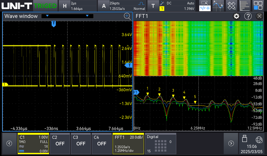 Built-in FFT spectrum analyzer for harmonics and EMI investigation
Mixed-Signal Debugging — 16 Optional Digital Channels
16 optional digital channels add mixed-signal debugging via the UT-M26 logic probe pod. The digital traces display alongside analog channels with full time correlation — see I²C bus traffic and analog ADC output on the same time axis, or watch a control firmware state machine drive the gate signals on a switching power stage.
Time-correlated mixed-signal views are essential for debugging the boundary between firmware and analog hardware. A timing-violation that's invisible on either domain alone often becomes obvious when you can see the digital command and the analog response on the same trace.
56 Automated Measurements with Statistics
56 automated measurements cover time, voltage, frequency, and power-quality parameters with statistical analysis (min, max, mean, standard deviation) and trend graphs over long captures. For QA work and bench characterization, the statistical view is more useful than the instantaneous reading — it tells you whether a parameter is drifting, jittering, or holding steady.
Pass/fail mask testing applies user-defined tolerance bands across captured waveforms — useful for rapid go/no-go testing during bring-up, or for validating board-to-board consistency in small-volume production.
Touch UI and Connectivity
The 7-inch 1024×600 capacitive touchscreen supports pinch-to-zoom, drag, and gesture navigation across waveforms, menus, and measurement readouts. For students and lab newcomers, the touch interface lowers the barrier to advanced features that are buried behind menu trees on older instruments.
Connectivity covers USB Host, USB Device, LAN, AUX Out, and HDMI, plus dedicated AWG Generator Output (-S models). The HDMI output drives an external display for classroom demonstration, and LAN connectivity integrates the instrument into automated test scripts and remote-access workflows.
Applications
R&D Engineer (Embedded / Hardware Design)
- Power-Stage Design Verification — Sweep a control loop with the integrated AWG, run Bode plot analysis on the response, and verify gain/phase margins without leaving the instrument. The 12-bit ADC at full 250 MHz captures the switching waveform on the same time axis.
- Mixed-Signal Debug — Time-correlated analog and digital views with the optional UT-M26 logic pod. Track firmware state machines against analog responses on the same trace.
- Protocol Investigation — All standard embedded protocols included; no license fees for automotive (CAN, CAN-FD, LIN), industrial (RS-422/485), or audio buses.
- Signal Integrity Spot Checks — FFT analysis identifies harmonics, clock spurs, and EMI sources without switching to a separate spectrum analyzer.
Power Electronics Engineer
- Closed-Loop Power-Supply Characterization — The integrated AWG drives the control loop while Bode plot analysis measures the response, replacing a multi-instrument workflow with a single-instrument measurement.
- Soft-Start and Fault-Recovery Capture — 100 Mpts deep memory records the entire transient at sample-rate resolution; no piecing together multi-pass captures.
- Ripple and Noise on DC Rails — The 12-bit ADC resolves µV-scale ripple on multi-hundred-volt DC rails — measurements that an 8-bit scope fundamentally cannot make.
- Harmonic Content Investigation — Built-in FFT to 1 Mpts identifies switching-frequency content, harmonics, and coupled noise sources.
Accessories & In the Box
Included with the Instrument
- MSO1254HD-S oscilloscope
- 4 × passive probes (1:1 / 10:1 switchable, bandwidth matched to instrument)
- USB cable (USB-A to USB-B)
- Power cord (region-appropriate)
- Quick-start guide
- Factory calibration certificate
Recommended Accessories
- UT-M26 — 16-channel logic probe pod for mixed-signal debugging
- UT-P07A — 500 MHz passive probe for higher-bandwidth applications
- UT-P20, UT-P21, UT-V23 — high-voltage passive probes
- UT-P30, UT-P31, UT-P32, UT-P33 — differential probes for floating measurements
- UT-P40, UT-P41, UT-P42, UT-P43, UT-P44 — current probes for power-stage and switching-loss measurement
- UT-ISOT — isolation transformer for safe line-powered measurements
- UT-M13X — oscilloscope demo board for protocol decoding practice and curriculum modules
Need only the basic platform without the AWG? See the MSO1254HD. Need a 150 MHz value-tier option with AWG? See the MSO1154HD-S.
Frequently Asked Questions
What protocols are included with the MSO1254HD-S?
RS-232/UART, I²C, SPI, RS-422, RS-485, CAN, CAN-FD, LIN, and Audio decoding are included standard at no additional cost. All supported protocols are available out of the box — no optional licenses required.
What is the advantage of native 12-bit resolution?
A 12-bit ADC provides 4,096 vertical levels compared to 256 for an 8-bit scope — sixteen times greater detail. This reveals small signals riding on large ones, reduces quantization noise, and improves measurement accuracy on low-amplitude signals like power-supply ripple, sensor outputs, and precision analog circuits. R12™ holds the 12-bit resolution at the full bandwidth and sample rate, with no ERES averaging or sample-rate trade-off.
Can I add digital channels for mixed-signal debugging?
Yes. The UT-M26 logic probe pod adds 16 digital channels for time-correlated analog and digital views.
What waveforms can the built-in AWG produce?
The integrated 1-channel 25 MHz arbitrary waveform generator outputs sine, square, ramp, pulse, noise, DC, and user-defined arbitrary waveforms. It also enables the Bode plot function for automated frequency-response measurement.
How does the MSO1254HD-S compare to the higher-bandwidth UPO2000HD or MSO3000HD scopes?
The MSO1000HD platform shares the same R12™ 12-bit ADC architecture, Ultra Phosphor 3.0 acquisition, and standard-included protocol decoding as the UPO2000HD and MSO3000HD families. The differences are bandwidth (150–250 MHz here vs 100–500 MHz on UPO2000HD and 350–1000 MHz on MSO3000HD), capture rate (1,000,000 wfms/s in Sequence Mode here vs 1,500,000 wfms/s on MSO3000HD), and the front-panel form factor. For embedded prototyping and mid-tier power-electronics work, the MSO1000HD platform delivers the same architectural advantages at a lower price point.
Is the firmware field-upgradable?
Yes. Firmware updates are free over the product's lifetime and install via USB drive or LAN transfer.
Part of the MSO1000HD oscilloscope series. See the series page to compare bandwidth and channel options across the lineup.
Warranty
This instrument is backed by UNI-T's 3+2 Year Warranty — 3 years of standard coverage, plus 2 additional years free when you register your product. That's 5 years of total protection at no extra cost.
The warranty covers manufacturing defects and component failures under normal use conditions. UNI-T instruments are built for professional daily use, and our warranty reflects that commitment to long-term reliability.
| Analog Bandwidth | 250MHz |
|---|---|
| Channels | 4Ch+16D (opt) |
| Sample Rate | 2.5GSa/s |
| Memory Depth | 100Mpts |
| Vertical Resolution | 12 bits |
| Built-in Signal Generator | Included |
| Digital Channels | Optional |
| Touch Screen | ✓ |
| Instrument Type | HD MSO |
Features
- Frequency Counter
- Digital Voltmeter
Full specifications (24)
| Details | |||||
|---|---|---|---|---|---|
| Waveform Capture Rate |
|
||||
| Input Impedance | 1 MΩ | ||||
| Vertical Scale (1 MΩ) | 500μV/div to 10V/div | ||||
| Automated Measurements | 56 | ||||
| Bus Protocols (Standard) | RS232|UART|RS422|RS485|I2C|SPI|CAN|CAN-FD|LIN|Audio | ||||
| Protocol Decoders | 7 | ||||
| Measurement Parameters | 56 | ||||
| Fft Points | 1Mpts | ||||
| Features | |||||
| Frequency Counter Bits | 7-digit | ||||
| Square / Pulse Frequency | 10MHz | ||||
| Power Analysis | 12 | ||||
| Modulation Types | AM|FM | ||||
| Dvm Bits | 4-digit | ||||
| AWG Channels | 1 | ||||
| AWG Frequency | 25 MHz | ||||
| Arb Memory Depth | 4kpts | ||||
| Standard Waveforms | Sine|Square|Ramp|Pulse|Noise|DC|Arbitrary | ||||
| General Information | |||||
| Display Size | 7in | ||||
| Display Type | TFT LCD | ||||
| Interface | USB|LAN|AUX|HDMI|Gen Out | ||||
| Dimensions (W×H×D) | 282 × 175 × 49 mm | ||||
| Weight | 1.56 kg | ||||
| Warranty | 3+2 years | ||||
| Certifications | CE|cETLus | ||||
Data Sheets and Manuals
Older firmware versions (1)
Check your instrument’s hardware revision before updating firmware — different hardware revisions take different builds.
Authentic UNI-T accessories are an affordable way to extend the functionality of your instrument.
Passive Probes 11

UT-P01 25 MHz 10:1 General Purpose Oscilloscope Probe
$15.99
UT-P03 60 MHz 10:1 General Purpose Oscilloscope Probe
$18.99
UT-P04 100 MHz 10:1 General Purpose Oscilloscope Probe
$15.99
UT-P05 200 MHz 10:1 General Purpose Oscilloscope Probe
$20.99
UT-P06 300 MHz 10:1 General Purpose Oscilloscope Probe
$37.99
UT-P07A 500 MHz 10:1 General Purpose Oscilloscope Probe
$51.99UT-P07B 500 MHz 10:1 General Purpose Oscilloscope Probe
$119.00
UT-P08A 350 MHz 10:1 General Purpose Oscilloscope Probe
$51.99
UT-P20 250 MHz 100:1 High Voltage Oscilloscope Probe
$56.99
UT-P21 50 MHz 1000:1 High Voltage Oscilloscope Probe
$430.00
UT-V23 High Voltage Scope Probe
$25.00Current Probes 6

UT-P40 DC-100 kHz 60A AC/DC Current Probe
$452.00
UT-P41 DC-100 kHz 100A AC/DC Current Probe
$595.00
UT-P4150 12 MHz High-Frequency DC/AC Current Probe
$2,529.00
UT-P42 150 kHz 200A AC/DC Current Probe
$459.00
UT-P43 DC-25 MHz 20A 100mV/A Current Probe
$956.00
UT-P44 DC-50 MHz 40A 50mV/A Current Probe
$1,695.00Differential Probes 6

UT-P30 100 MHz 10:1/100:1 Differential Oscilloscope Probe
$399.00
UT-P31 100 MHz 100:1/1000:1 Differential Oscilloscope Probe
$699.00
UT-P32 50 MHz 100:1/1000:1 Differential Oscilloscope Probe
$860.00
UT-P33 120 MHz 100:1/1000:1 Differential Oscilloscope Probe
$1,465.00
UT-P35 50 MHz 50:1/500:1 Differential Oscilloscope Probe
$395.00
UT-P36 100 MHz 200:1/2000:1 Differential Oscilloscope Probe
$459.00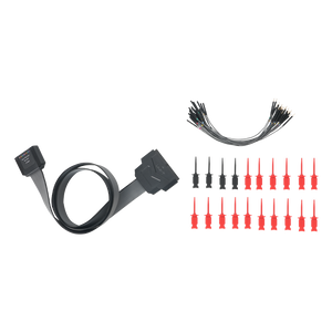
Other Accessories 2


I think the MSO1254HD-S is a powerhouse and Best in Class. This scope comes with everything that an Analog Engineer needs With the built in signal generator - Bode Plots can be made so filters, amplifiers, and power supplies can be evaluated. It also comes with a nice large set of buss decoders, e.g. CAN and I2C which are showing up everywhere. With the HDMI port a larger screen can be connected as well as a mouse and keyboard.

I bought this oscilloscope (with the signal generator option), plus the logic analyzer probe, at the 2026 Dayton Hamvention. I'm really impressed with the price vs. performance of the instrument as well as the warranty arrangement. Before seeing this at Hamvention, I thought I was going to have to settle for either a dual-channel 200MHz or quad-channel 100MHz scope from some of the other vendors. With four channels and 250MHz per channel, this will more than meet my needs as a hobbyist for RF designs through the six-meter band as well as general SPI/I2C commands for digitally controlled RF components.
I purchased this at the local New England Hamfest. Last year I bought a 3 Ghz Spectrum Analyzer. And then this year this new 12 Bit scope was available.
What I liked about this one is it is almost an all in one analyzer/scope. And it had the digital logics decodes I needed.