USG5000M Analog RF Generators
-
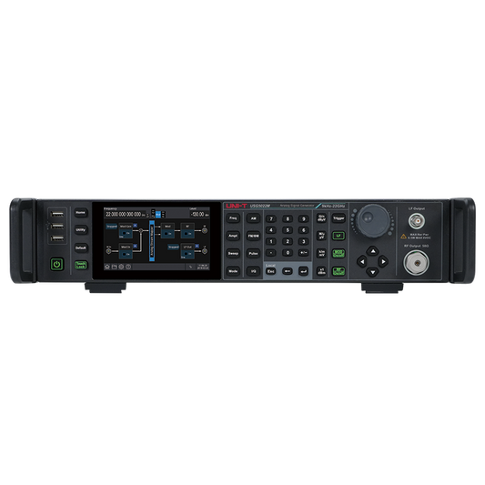
USG5014M14 GHz Analog RF Signal Generator
- Frequency Range: 9kHz - 14GHz
- Level Range: -135dBm - +25dBm
- Phase Noise: <-122dBc/Hz (1GHz@20kHz)
- Modulation Types: AM, FM, ΦM, Pulse
- LF Generator: Yes
Regular price $16,899.00Only 2 in stock -
USG5014M-P14 GHz Analog RF Signal Generator with Mechanical Attenuator
- Frequency Range: 9kHz - 14GHz
- Level Range: -135dBm - +25dBm
- Phase Noise: <-122dBc/Hz (1GHz@20kHz)
- Modulation Types: AM, FM, ΦM, Pulse
- LF Generator: Yes
Regular price $21,899.00Only 5 in stock -
USG5022M-P22 GHz Analog RF Signal Generator with Mechanical Attenuator
- Frequency Range: 9kHz - 22GHz
- Level Range: -135dBm - +25dBm
- Phase Noise: <-122dBc/Hz (1GHz@20kHz)
- Modulation Types: AM, FM, ΦM, Pulse
- LF Generator: Yes
Regular price $24,899.006 in stock
RF Signal Generator Buying Guide: Comprehensive Selection Guide for 2025
Introduction
Radio Frequency (RF) signal generators are essential test instruments for engineers and technicians working in wireless communications, 5G/6G development, aerospace, automotive radar, satellite communications, semiconductor testing, and research laboratories. These precision instruments produce controlled RF and microwave signals with specific characteristics vital for testing, calibrating, and characterizing RF systems and components. Understanding the difference between standard RF signal generators and advanced vector signal generators is crucial for making the right equipment investment.
This comprehensive buying guide will help you navigate the key specifications, features, and application requirements when selecting an RF or vector signal generator to ensure you choose the right instrument for your testing needs.
Understanding RF Signal Generator Types
Standard RF Signal Generators
Traditional RF signal generators produce continuous wave (CW) signals with analog modulation capabilities including AM (amplitude modulation), FM (frequency modulation), and ΦM (phase modulation). These instruments are ideal for basic RF testing, component characterization, and receiver sensitivity measurements.
Vector Signal Generators
Vector signal generators represent the next evolution in RF test equipment, offering both traditional analog modulation and advanced IQ modulation capabilities. These instruments can generate complex digital modulation formats including QAM (Quadrature Amplitude Modulation), PSK (Phase Shift Keying), FSK (Frequency Shift Keying), and ASK (Amplitude Shift Keying).
Vector signal generators are essential for testing modern wireless communication systems including 5G NR, LTE, WLAN, Bluetooth, IoT devices, and other digital communication standards. They provide three key advantages:
- Digital modulation capability: Generate real-world communication signals with precise control over both amplitude and phase
- Arbitrary waveform generation (ARB): Create custom signal scenarios and complex modulation schemes
- AWGN simulation: Add controlled Additive White Gaussian Noise for realistic receiver testing without additional equipment
When to choose a vector signal generator: If your applications involve testing modern wireless devices, digital communication receivers, or any system using digital modulation, a vector signal generator provides the flexibility and capability to handle both current and future testing requirements.
Key Specifications to Consider
Frequency Range and Band Coverage
The frequency range is perhaps the most critical specification when selecting an RF signal generator, as it determines which applications and wireless standards you can test.
Application-specific frequency requirements:
- Mobile communications (L/S-bands): 700 MHz - 6 GHz for cellular, LTE, 5G sub-6 GHz
- Wi-Fi testing (S/C-bands): 2.4 GHz, 5 GHz, and 6 GHz bands (Wi-Fi 6E)
-
Satellite communications:
- C-band: 4-8 GHz
- X-band: 8-12 GHz
- Ku-band: 12-18 GHz
- K-band: 18-27 GHz
- Automotive radar (Ku/K-bands): 24 GHz (short-range), 77 GHz, 79 GHz (long-range ADAS)
- 5G mmWave (Ka-band): 24-40 GHz and beyond
- 6G research: Extending into Ka-band and beyond (22+ GHz)
UNI-T Example: The USG3000V series (4.5-6.5 GHz) covers L, S, and C-band applications including most cellular, Wi-Fi, and lower-frequency satellite testing. For higher frequency applications, the USG5000V series extends to 14 GHz and 22 GHz, covering X, Ku, and K-bands for automotive radar, satellite communications, and 5G/6G mmWave development.
Future-proofing considerations: Select a generator with frequency range extending beyond your immediate needs. For example, if currently testing 5G sub-6 GHz systems, consider an instrument reaching into millimeter-wave frequencies to accommodate future 5G mmWave or 6G testing requirements.
Frequency resolution: Look for generators offering fine frequency resolution (0.001 Hz) for precise signal placement and accurate receiver testing.
Attenuator Type: Mechanical vs. Electronic
The type of attenuator significantly impacts performance characteristics and suitability for different applications. Understanding this distinction is crucial for selecting the right instrument.
Mechanical Attenuators (designated with "-P" suffix in UNI-T models):
Advantages:
- Superior level stability and repeatability over extended test periods
- Higher maximum output power (typically +23 to +25 dBm vs. +18 to +20 dBm)
- Better VSWR (Voltage Standing Wave Ratio) performance across frequency ranges
- More consistent power flatness across the full frequency range
- Enhanced durability and resistance to damage from excessive input power
Ideal applications:
- Production testing requiring consistent power levels
- Power amplifier characterization and compression testing
- Receiver sensitivity measurements requiring stable low-level signals
- Applications demanding maximum output power for driving DUTs
- Long-duration automated test sequences
Electronic Attenuators:
Advantages:
- Faster amplitude switching speed for high-speed automated testing
- No mechanical wear from repeated level changes
- Finer amplitude resolution in some implementations
- Generally lower cost
Ideal applications:
- High-speed automated test sequences with frequent level changes
- Applications requiring rapid amplitude modulation
UNI-T Example: The USG3065V-P and USG5014V-P models feature mechanical attenuators providing +24-25 dBm maximum output power and superior level accuracy, while standard USG3065V and USG5014V models with electronic attenuators offer +20 dBm output. For applications requiring maximum power and stability, the "-P" mechanical attenuator models are the preferred choice.
Output Power Range and Dynamic Range
A wide output power range provides exceptional testing flexibility, allowing you to simulate both weak and strong signals with a single instrument.
Dynamic range: The best RF signal generators offer dynamic ranges exceeding 150 dB, typically from approximately -135 dBm (ultra-low power for sensitive receiver testing) to +20 dBm or higher (for driving power amplifiers and system-level testing).
Maximum output power considerations:
- Higher output power (+23 to +25 dBm) is essential for testing receiver sensitivity thresholds, characterizing high-intercept amplifiers, and driving passive components with insertion loss
- Adequate output power eliminates the need for external amplifiers, reducing test complexity and measurement uncertainty
Minimum output power applications:
- Low output levels (down to -135 dBm) enable precise receiver sensitivity measurements
- Testing low-noise amplifiers and sensitive receivers
- Simulating weak signals for radar and satellite communication systems
UNI-T Example: Both USG3000V and USG5000V series provide an industry-leading -135 dBm to +25 dBm output range (mechanical attenuator models), delivering 160 dB of dynamic range. This exceptional range covers everything from ultra-sensitive receiver testing to high-power component characterization with a single instrument, eliminating the need for external attenuators or amplifiers.
Signal Purity: Phase Noise and Spectral Performance
Signal purity directly affects measurement accuracy and is critical for testing high-performance receivers, radar systems, and communication devices.
Phase noise: Lower phase noise performance is essential for:
- Testing receivers with high sensitivity and selectivity requirements
- Radar system characterization where close-in phase noise affects target detection
- Oscillator and PLL (Phase-Locked Loop) testing
- High-order modulation schemes (64-QAM, 256-QAM) which are sensitive to phase noise
Target specification: Professional-grade instruments should offer phase noise performance of -120 dBc/Hz or better at 20 kHz offset from a 1 GHz carrier. Premium instruments achieve -122 dBc/Hz or better.
UNI-T Example: Both USG3000V and USG5000V series achieve <-122 dBc/Hz @ 1 GHz, 20 kHz offset (typical), matching or exceeding phase noise performance of premium signal generators at a fraction of the cost. This exceptional performance ensures accurate characterization of even the most sensitive receivers and high-order modulation schemes.
Harmonics and spurious signals: Lower harmonic content and spurious signal levels ensure your test signals don't introduce unwanted frequency components that could affect measurement accuracy. Look for harmonic suppression of -40 dBc or better.
Vector Modulation Capabilities
For modern wireless communication testing, vector signal generation capability is increasingly essential rather than optional.
Analog modulation (standard on all generators):
- AM, FM, ΦM for basic signal generation
- Internal and external modulation sources
- Pulse modulation for radar and burst transmission testing
Digital vector modulation (available on vector signal generators):
- Real-time IQ modulation for generating complex digital signals
- Standard modulation formats: QPSK, QAM (16-, 64-, 256-QAM), PSK, FSK, ASK
- Protocol-specific signal generation: 5G NR, LTE, WLAN, Bluetooth, WCDMA, IoT standards
- Modulation bandwidth: Critical specification determining the data rates you can simulate (look for 150 MHz or higher for 5G applications)
Arbitrary Waveform (ARB) capabilities:
- Real-time modulation mode for immediate signal generation
- Local ARB mode for playing back stored waveforms
- Remote ARB mode for integration with signal simulation software
- ARB memory depth (500 MSa or more enables complex, long-duration scenarios)
- Multi-segment playback with repeat capabilities
AWGN (Additive White Gaussian Noise) simulation:
- Essential feature for receiver testing
- Simulates real-world channel interference without external noise sources
- Precise control of signal-to-noise ratio (SNR)
- Integrated noise power measurement
UNI-T Example: The USG3000V and USG5000V series include comprehensive vector modulation with 150 MHz IQ modulation bandwidth, supporting all major digital modulation formats. The integrated AWGN capability allows precise receiver testing with controlled interference simulation. ARB memory up to 500 MSa with multi-segment playback (up to 1,024 segments) and repeat count up to 65,535 enables complex test scenarios. When paired with Signal Studio software, these generators can produce standards-compliant signals for 5G NR, WLAN, LTE, Bluetooth, and IoT applications.
Vector modulation accuracy metrics:
- EVM (Error Vector Magnitude): Lower is better; look for <0.5% for QPSK, <1% for 64-QAM
- ACPR (Adjacent Channel Power Ratio): Important for wireless transmitter testing; look for -55 dBc or better for 5G NR
UNI-T Example: USG5000V series achieves QPSK EVM of 0.4% (typical) at 2 GHz and 5G NR ACPR of -55 dBc (typical) at 3.8 GHz carrier, providing the accuracy needed for both R&D characterization and production testing of communication devices.
Amplitude Accuracy and Level Flatness
Amplitude accuracy is vital for reliable power measurements, especially when testing receiver sensitivity or transmitter output levels.
Absolute level accuracy: Typically specified in dB (e.g., ±0.7 dB), with lower values indicating better accuracy. This specification affects:
- Receiver sensitivity measurements
- Transmitter output power verification
- Component gain/loss characterization
- System-level performance validation
Level flatness: Consistency of output power across the frequency range minimizes the need for frequency-dependent corrections.
Temperature stability: Accuracy specifications are typically given for a specific temperature range (e.g., 0°C to +50°C). Consider your operating environment when evaluating this specification.
UNI-T Example: USG3000V and USG5000V series both specify ≤0.7 dB amplitude accuracy (typical), providing the precision needed for accurate DUT characterization across all frequency ranges without extensive calibration corrections.
Additional Features and Considerations
Built-in Function Generator
Many modern RF signal generators include integrated arbitrary waveform generators that provide significant added value for modulation sources and general-purpose testing.
Key function generator specifications:
- Frequency range: Higher bandwidth enables more versatile testing (50 MHz is significantly better than 1-10 MHz found in many competitors)
- Waveform types: Sine, square, triangle, ramp, pulse, arbitrary waveforms
- Applications: Creating modulation sources, simulating baseband signals, general lab testing
UNI-T Example: Both USG3000V and USG5000V series include a 50 MHz function/arbitrary waveform generator—16 to 50 times higher bandwidth than competitive offerings (which typically provide 1-10 MHz). This integrated capability eliminates the need for a separate function generator in many applications, reducing test setup complexity and equipment costs.
Pulse Modulation Capabilities
For radar testing, automotive radar development, and pulsed communication systems, pulse modulation capability is essential.
Key pulse specifications:
- Minimum pulse width (look for 40 ns or better for automotive radar)
- Pulse width resolution (10 ns enables precise control)
- On/off ratio (70-80 dB provides good dynamic range)
- Pulse train and sequence capabilities
UNI-T Example: Optional pulse modulation on USG3000V and USG5000V series provides on/off ratios up to 80 dB with customizable pulse sequences. The narrow pulse generator option supports pulse widths as short as 40 ns with 10 ns resolution—ideal for automotive millimeter-wave radar testing at 24 GHz and 77 GHz.
Sweep Capabilities
Comprehensive sweep functions enable automated characterization of frequency-dependent behavior in filters, amplifiers, antennas, and other RF components.
Sweep types to look for:
- Frequency sweep (characterize filter responses, antenna patterns)
- Amplitude sweep (compression testing, gain linearity)
- Combined frequency and amplitude sweep
- List sweep for testing at discrete frequency points
Sweep parameters: Consider range of step sizes, dwell times, and triggering options for integration into automated test systems.
UNI-T Example: USG3000V and USG5000V series support multiple sweep modes including list/step frequency sweep, amplitude sweep, and combined frequency+amplitude sweep with both linear and logarithmic modes, plus customizable list sweep for testing at specific frequency points.
Connectivity and Remote Control
Modern test equipment requires flexible connectivity for both manual operation and integration into automated test systems.
Physical interfaces:
- LAN/Ethernet: Standard for network-based test systems
- USB: Convenient for direct PC connection
- GPIB (IEEE-488): Often required for legacy test systems
Remote control considerations:
- SCPI (Standard Commands for Programmable Instruments) command compatibility
- Available drivers for common programming environments (LabVIEW, MATLAB, Python)
- Web-based remote control interface
User interface features:
- Touchscreen displays improve operational efficiency
- Intuitive navigation reduces training time and operator errors
- Signal flow diagram interfaces help visualize signal path and settings
UNI-T Example: USG3000V and USG5000V series feature 5-inch capacitive touchscreen displays (800×480 resolution) with signal flow diagram-guided interface for intuitive operation. Standard connectivity includes LAN and USB, with optional GPIB for integration into existing test systems. Full SCPI command support enables integration into automated test environments.
Reference Clock Stability
Internal reference frequency stability directly affects measurement accuracy and long-term reliability.
Key reference specifications:
- Initial calibration accuracy: Look for ±40 ppb (parts per billion) or better
- Aging rate: ≤±0.2 ppm/year ensures long-term stability
- Temperature effects: ≤±10 ppb minimizes environmental sensitivity
- External reference input: 10 MHz input allows synchronization with higher-stability references
Clock source type: OCXO (Oven-Controlled Crystal Oscillator) provides superior stability compared to standard crystal oscillators, with minimal drift over temperature and time.
UNI-T Example: USG3000V and USG5000V series include standard OCXO reference oscillators with ≤±40 ppb initial calibration accuracy and ≤±0.2 ppm/year aging rate. This provides exceptional long-term frequency stability, reducing recalibration requirements and maintaining measurement accuracy.
Form Factor and Physical Considerations
The instrument's physical dimensions and mounting options may be important depending on workspace constraints and application requirements.
Size considerations:
- 2U rack height is standard for professional test equipment
- Bench-top operation with handle and tilt feet for manual use
- Rack-mount capability for integration into test systems
Portability: If moving the generator between locations, consider weight (typically <20 kg for 2U instruments) and available handles.
UNI-T Example: USG3000V and USG5000V series feature standard 2U rack height (449×100×474 mm) with weights <20 kg, suitable for both bench-top and rack-mount installations. Integrated handles and tilt feet facilitate manual operation and portability.
Warranty and Support
Investing in quality test equipment from a reputable manufacturer ensures long-term reliability and support.
Warranty coverage: While standard warranties are typically 1-3 years, some manufacturers offer extended warranty programs providing significant long-term value.
Calibration interval: Professional RF test equipment typically requires annual calibration to maintain specified accuracy.
Technical support: Consider availability of application support, documentation, and repair services.
UNI-T Example: UNI-T provides an exclusive 3+2-year warranty on RF signal generators (5 years total), significantly exceeding the industry-standard 1-3 years. This extended warranty demonstrates long-term commitment to product quality and provides valuable cost protection for your test equipment investment.
Application-Specific Considerations
5G and 6G Wireless Communications Testing
Testing next-generation wireless systems requires advanced vector signal generation capabilities and appropriate frequency coverage.
Key requirements:
-
Frequency coverage:
- 5G sub-6 GHz (FR1): Requires coverage to at least 6 GHz
- 5G mmWave (FR2): 24-40 GHz and beyond
- 6G research: Extending to 22+ GHz and higher
- Modulation bandwidth: 150 MHz or greater for wide carrier bandwidths
- Vector modulation: Essential for generating 5G NR waveforms with complex modulation schemes
- AWGN capability: Critical for realistic receiver testing
- Signal purity: Low phase noise and excellent ACPR for high-order modulation
UNI-T Example: For 5G sub-6 GHz testing, the USG3065V (up to 6.5 GHz) provides complete coverage of FR1 bands with 150 MHz modulation bandwidth and comprehensive vector modulation. For 5G mmWave and 6G research, the USG5014V and USG5022V extend coverage to 14 GHz and 22 GHz respectively, covering critical development frequencies with the same vector capabilities.
Satellite Communications and Aerospace
Satellite communication testing spans multiple frequency bands requiring appropriate generator coverage and signal purity.
Frequency band requirements:
- C-band (4-8 GHz): Commercial satellite communications
- X-band (8-12 GHz): Military satellite communications, weather radar
- Ku-band (12-18 GHz): Broadcast satellites, VSAT
- K-band (18-27 GHz): Satellite communications, automotive radar
Additional requirements:
- Excellent phase noise for receiver testing
- Wide dynamic range for various link budget scenarios
- Pulse modulation for radar applications
- High frequency stability
UNI-T Example: The USG5014V (14 GHz) and USG5022V (22 GHz) provide complete coverage of C, X, Ku, and K-bands for satellite communication testing, with <-122 dBc/Hz phase noise and -135 to +25 dBm output range suitable for both component-level and system-level testing.
Automotive Radar and ADAS Testing
Automotive radar development for Advanced Driver Assistance Systems (ADAS) requires specific frequency coverage and pulse capabilities.
Automotive radar frequencies:
- 24 GHz: Short-range radar (parking assistance, blind spot detection)
- 77-79 GHz: Long-range radar (adaptive cruise control, collision avoidance)
Key requirements:
- Frequency coverage to at least 22 GHz for 24 GHz radar testing and component development
- Pulse modulation with narrow pulse capability (40 ns minimum)
- High output power for component testing
- Low phase noise for chirp signal generation
UNI-T Example: The USG5022V (22 GHz) with optional narrow pulse modulation (40 ns minimum width, 10 ns resolution) provides comprehensive capability for 24 GHz automotive radar component testing. The optional pulse modulation with 80 dB on/off ratio and customizable pulse sequences enables realistic radar signal simulation.
RF Component Characterization
Testing filters, amplifiers, mixers, antennas, and other RF components requires flexible signal generation and comprehensive sweep capabilities.
Requirements:
- Wide frequency range covering component operating frequencies
- Excellent amplitude accuracy for precise gain/loss measurements
- Comprehensive sweep functions for frequency response characterization
- High maximum output power for driving passive components
- Low minimum output power for sensitive amplifier testing
UNI-T Example: The USG3000V series provides comprehensive component testing from 9 kHz to 6.5 GHz with ≤0.7 dB amplitude accuracy and -135 to +25 dBm range. Multiple sweep modes enable automated filter response measurements, amplifier gain characterization, and antenna pattern testing.
Research, Development, and Education
Laboratory and educational applications benefit from versatile instruments offering comprehensive capabilities at accessible price points.
Key considerations:
- Wide range of features supporting diverse experiments
- Intuitive user interface for students and researchers
- Comprehensive modulation options for teaching digital communications
- Cost-effectiveness balancing performance with budget constraints
- Reliable long-term operation
UNI-T Example: USG3000V and USG5000V series combine professional specifications with accessible pricing, making advanced vector signal generation available for university laboratories and research institutions. The touchscreen interface and signal flow diagram reduce learning curve, while comprehensive modulation capabilities support education in modern wireless communications.
Cost Considerations and Value Analysis
RF signal generators span a wide price range based on frequency coverage, performance specifications, and feature sets.
Performance tiers:
- Entry-level (< $5,000): Limited frequency range (<4 GHz), basic modulation, suitable for simple testing
- Mid-range ($8,000-$20,000): Professional frequency coverage (up to 6-22 GHz), vector modulation, comprehensive features
- Premium ($25,000-$100,000+): Extended frequency ranges, ultimate performance specifications, premium brand
Feature value assessment:
- Vector modulation capability: Essential for modern wireless testing; can eliminate need for separate equipment
- Wide dynamic range: Reduces need for external attenuators and amplifiers
- Integrated function generator: Eliminates separate instrument requirement
- Extended warranty: Provides long-term cost protection
Total cost of ownership:
- Annual calibration costs
- Maintenance and repair
- Software licensing (if required)
- Training and documentation
UNI-T Example: USG3000V series (4.5-6.5 GHz) and USG5000V series (14-22 GHz) position in the mid-range pricing tier while offering specifications comparable to premium instruments: <-122 dBc/Hz phase noise, -135 to +25 dBm range, 150 MHz modulation bandwidth, 50 MHz integrated function generator, and comprehensive vector modulation. The exclusive 5-year warranty significantly improves total cost of ownership compared to standard 1-3 year warranties offered by competitors.
Conclusion
Selecting the right RF or vector signal generator requires careful consideration of your current testing requirements, future application needs, and budget constraints. Key decision factors include:
- Frequency range: Choose coverage appropriate for your applications with room for future growth
- Vector capability: Essential for testing modern digital wireless systems
- Output power range: Wide dynamic range (-135 to +25 dBm) eliminates need for additional equipment
- Signal purity: Phase noise <-122 dBc/Hz enables testing of sensitive receivers and high-order modulation
- Attenuator type: Mechanical attenuators provide superior performance for production testing and high-power applications
- Modulation bandwidth: 150 MHz or higher for 5G and advanced wireless applications
- Additional features: Integrated function generator, AWGN, pulse modulation, sweep capabilities
- Warranty and support: Extended warranty coverage provides long-term value
Modern vector signal generators like the UNI-T USG3000V and USG5000V series combine professional-grade specifications with mid-range pricing, offering exceptional value for laboratories, production facilities, and research institutions. Features including comprehensive vector modulation, industry-leading dynamic range, integrated 50 MHz function generator, and exclusive 5-year warranty make these instruments compelling choices for engineers requiring reliable, accurate signal generation across a wide range of applications.
Investing in a quality RF vector signal generator from a reputable manufacturer ensures the accuracy, reliability, and flexibility needed to support your RF testing requirements today and into the future—whether you're developing next-generation 5G/6G wireless systems, testing automotive radar components, characterizing satellite communication equipment, or conducting advanced RF research.
For more information about RF signal generators and vector signal generation capabilities, visit UNI-T Instruments or contact your local distributor.