


MSO3354E-S | 350 MHz 4+16Ch Mixed Signal Oscilloscope with Signal Generator
Overview
The MSO3354E is a 350 MHz mixed signal oscilloscope with 4 analog channels and 16 digital channels (logic analyzer included). It samples at 2.5 GSa/s with 250 Mpts memory depth and captures waveforms at up to 200,000 wfms/s on an 8-inch capacitive touchscreen. A built-in 50 MHz arbitrary waveform generator provides stimulus signals for closed-loop testing without external equipment. All MSO/UPO3000E-series instruments share the same platform — the same sample rate, memory, and measurement engine — with differences only in bandwidth, channel count, and included accessories.
The oscilloscope provides 36 automated measurements with statistics, advanced triggering (edge, pulse width, slope, video, pattern, and area trigger), Bode plot analysis for power supply loop characterization, and web-based remote control via LAN. Serial bus protocol decoding for RS-232, UART, I²C, SPI, CAN, CAN-FD, LIN, and FlexRay is available as optional software licenses.
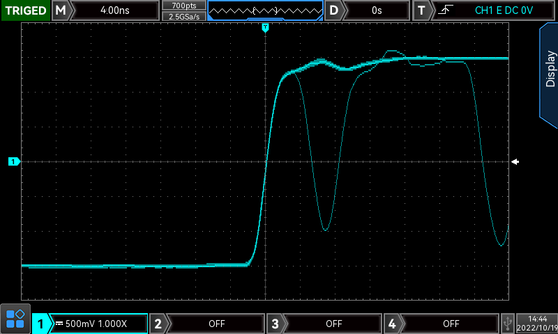
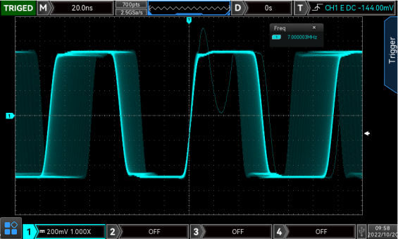 200,000 wfms/s capture rate reveals infrequent anomalies
Key Features
- 350 MHz Bandwidth, 4 Analog Channels — Four-channel capture at up to 350 MHz for mixed-signal debugging and signal analysis.
- 2.5 GSa/s Sample Rate — Captures fast edges and high-frequency content with accurate timing resolution.
- 250 Mpts Memory Depth — Deep memory for capturing long signal records without reducing sample rate.
- 200,000 wfms/s Capture Rate — Fast acquisition reveals infrequent glitches, runts, and timing violations that slower scopes miss.
- 16 Digital Channels (Logic Analyzer Included) — Mixed-signal debugging with time-correlated analog and digital views. Logic probe pod included.
- Built-In 50 MHz Signal Generator — Arbitrary waveform generator output for stimulus-response testing without external equipment.
- 36 Automated Measurements — Time, voltage, frequency, and statistical measurements with min/max/average/standard deviation tracking.
- Area Trigger — Draw a region on screen and trigger when a waveform enters or exits it — effective for isolating anomalies in complex signals.
- Bode Plot Analysis — Automated frequency response measurement for characterizing power supply control loops and filter circuits.
- 8-Inch Capacitive Touchscreen — Pinch, zoom, drag, and gesture navigation for efficient waveform interaction.
- Web Remote Control — Access the oscilloscope interface from any browser on the LAN — no software installation required.
- Connectivity — USB, LAN, VGA, EXT trigger, AUX output.
Deep Memory for Complete Signal Capture
With 250 Mpts of memory depth, the oscilloscope maintains its full 2.5 GSa/s sample rate across wide time base settings. This means you can capture an entire communication sequence, a full power-on cycle, or a long servo motor control loop without aliasing or missing events. Zoom into any portion of the captured record to examine details at full resolution.
200,000 wfms/s capture rate reveals infrequent anomalies
Built-In Signal Generator
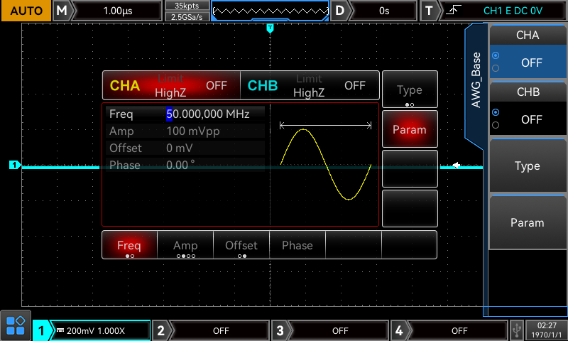
The 50 MHz arbitrary waveform generator outputs sine, square, ramp, pulse, noise, and user-defined arbitrary waveforms directly from the oscilloscope. Use it to inject test signals into a circuit and capture the response on the scope channels simultaneously — ideal for characterizing filters, amplifiers, and feedback loops without a separate signal generator on the bench.
Built-in arbitrary waveform generator for stimulus-response testing
Bode Plot for Loop Analysis
The Bode plot function sweeps the built-in signal generator across a frequency range while measuring gain and phase on the oscilloscope input. The result is a frequency response plot displayed directly on screen — essential for characterizing power supply feedback loops, verifying filter rolloff, and measuring amplifier bandwidth. Requires the -S model or external signal source.
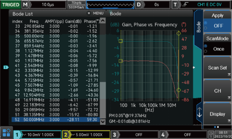 Bode plot analysis for power supply loop characterization
Mixed-Signal Debugging
The 16 digital channels display alongside analog traces with full time correlation, letting you see bus activity and analog behavior on the same time axis. This is critical for debugging embedded systems where a software command on I²C triggers an analog response — you need to see both to understand the system. The logic probe pod is included with all MSO models.
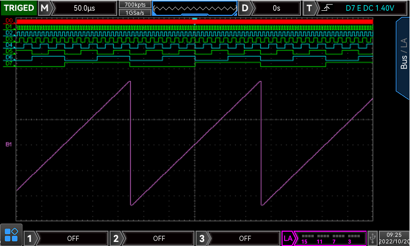 16-channel logic analyzer view correlated with analog traces
Advanced Triggering and Area Trigger
Beyond standard edge triggering, the MSO/UPO3000E supports pulse width, slope, video, pattern, and timeout triggers for isolating specific signal conditions. The area trigger lets you draw a box on screen and trigger when a waveform enters or exits it — particularly effective for catching anomalies in signals where you know what the waveform should look like but not exactly when the fault will occur.
Area trigger for isolating anomalies in complex signals
Web-Based Remote Control
Connect the oscilloscope to your LAN and access the full interface from any web browser — no dedicated software installation required. Adjust settings, view waveforms, capture screenshots, and transfer data remotely. This is useful for rack-mounted test setups, shared lab instruments, or situations where the oscilloscope is physically difficult to access.
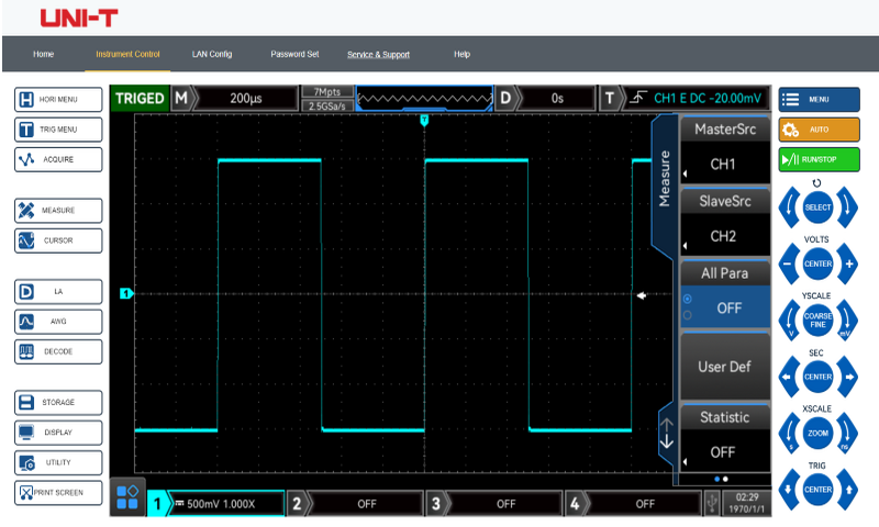 Web-based remote control from any browser on the LAN
Professional Applications
- Embedded Systems Development — Debug microcontroller firmware with time-correlated analog and digital views. Decode SPI, I²C, UART, and CAN bus traffic alongside power rails and clock signals.
- Power Electronics — Capture switching waveforms with deep memory, characterize control loop stability with Bode plot analysis, and trigger on specific voltage or timing conditions.
- Multi-Channel Signal Analysis — Four analog channels for simultaneous capture of input, output, reference, and feedback signals in complex circuits.
- Education and Training — The touchscreen interface and automated measurements lower the barrier for students learning oscilloscope operation, while the advanced features support upper-level lab coursework.
- Manufacturing and Quality — Automated measurements with pass/fail limits, web remote control for rack-mounted setups, and data export for test documentation.
Frequently Asked Questions
Are serial bus protocol decodes included?
No. Protocol decoding for RS-232, UART, I²C, SPI, CAN, CAN-FD, LIN, and FlexRay is available as optional software licenses. See the MSO/UPO3000E series page for available decode options.
What waveforms can the built-in signal generator produce?
The -S models include a 50 MHz arbitrary waveform generator that outputs sine, square, ramp, pulse, noise, DC, and user-defined arbitrary waveforms. It also enables the Bode plot function for automated frequency response measurement.
What is the difference between MSO and UPO models?
MSO models include the 16-channel logic probe pod in the box. UPO models are the same oscilloscope without the logic pod — you can add it later with the UT-M15 and LA16 software license. All other specifications are identical between MSO and UPO models at the same bandwidth and channel count.
Can I upgrade the bandwidth later?
No. The bandwidth is fixed at the factory. Choose the bandwidth you need at purchase — 350 MHz for this model. The 500 MHz and 350 MHz models share the same chassis and feature set.
Part of the MSO/UPO3000E oscilloscope series. All models share the same 2.5 GSa/s sample rate, 250 Mpts memory, and measurement engine. See the series comparison table to find the right combination of bandwidth, channels, and accessories for your application.
Data Sheets and Manuals
Software / Firmware Downloads
Authentic UNI-T accessories are an affordable way to extend the functionality of your instrument.
MSO/UPO3000 Options 12
Need to add specific functionality to your UNI-T instrument? Here are our options for specific applications and measurement types. Have a question? Contact us at 888-668-UniT (8648).

MSO/UPO3000CS-AUTO Decode Options Bundle (Includes CAN, CAN-FD, LIN, FlexRay)
$475.00
MSO/UPO3000CS-BND Decode Options Bundle (Includes EMBD and Auto)
$715.00
MSO/UPO3000CS-CAN Auto serial bus trigger and analysis-CAN
$236.00
MSO/UPO3000CS-CAN FD Auto serial bus trigger and analysis-CAN-FD
$236.00
MSO/UPO3000CS-COM PC serial bus trigger and analysis (RS232/UART)
$236.00
MSO/UPO3000CS-EMBD Serial bus trigger and decode options (includes RS232, UART, I2C, SPI)
$475.00
MSO/UPO3000CS-FlexRay Auto serial bus trigger and analysis-FlexRay
$236.00
MSO/UPO3000CS-I2C Embedded serial bus trigger and analysis-I2C
$236.00
MSO/UPO3000CS-LIN Auto serial bus trigger and analysis-LIN
$236.00
MSO/UPO3000CS-SPI Embedded serial bus trigger and analysis-SPI
$236.00
MSO3000CS-S-BODE Bode Plot Option for -S models
$299.00
UPO3000CS/E-LA16 Logic Analyzer Software Option (requires UT-M15)
$345.00Passive Probes 10

UT-P01 25MHz 10:1 General Purpose Oscilloscope Probe
$15.00
UT-P03 60MHz 10:1 General Purpose Oscilloscope Probe
$18.00
UT-P04 100MHz 10:1 General Purpose Oscilloscope Probe
$15.00
UT-P05 200MHz 10:1 General Purpose Oscilloscope Probe
$20.00
UT-P06 300MHz 10:1 General Purpose Oscilloscope Probe
$36.00
UT-P07A 500MHz 10:1 General Purpose Oscilloscope Probe
$49.00
UT-P08A 350MHz 10:1 General Purpose Oscilloscope Probe
$49.00
UT-P20 250MHz 100:1 High Voltage Oscilloscope Probe
$54.00
UT-P21 50MHz 1000:1 High Voltage Oscilloscope Probe
$410.00
UT-V23 high Voltage Scope Probe
$24.00Current Probes 6

UT-P40 DC-100kHz 60A AC/DC Current Probe
$430.00
UT-P41 DC-100kHz 100A AC/DC Current Probe
$567.00
UT-P4150 12MHz High-Frequency DC/AC Current Probe
$2,529.00
UT-P42 150kHz 200A AC/DC Current Probe
$437.00
UT-P43 DC-25MHz 20A 100mV/A Current Probe
$910.00
UT-P44 DC-50MHz 40A 50mV/A Current Probe
$1,615.00Differential Probes 6

UT-P30 100MHz 10:1/100:1 Differential Oscilloscope Probe
$379.00
UT-P31 100MHz 10:1/100:1 Differential Oscilloscope Probe
$666.00
UT-P32 50MHz 100:1/1000:1 Differential Oscilloscope Probe
$820.00
UT-P33 120MHz 10:1/100:1 Differential Oscilloscope Probe
$1,396.00
UT-P35 50MHz 50:1/500:1 Differential Oscilloscope Probe
$376.00


